Technical drawing is an essential skill across all professional sectors in Kenya, enabling clear communication of ideas, designs, and plans. Whether in healthcare facilities, county government offices, or retail businesses, accurate drawings ensure that concepts are understood and executed correctly. This chapter focuses on producing plane geometry drawings by mastering the types of lines used, which form the foundation of technical communication in any workplace.
2.1 Types of lines in drawings
In technical drawings, lines are fundamental elements that convey specific information about shapes, boundaries, and features. Understanding the standardized types of lines and their correct application is crucial for producing clear, precise, and professional drawings. Kenyan workplaces such as universities, SACCOs, and hospitals rely on these conventions to avoid misinterpretation and ensure consistency.
2.1.1 Boarder lines
Boarder lines define the limits of the drawing sheet and separate the drawing area from the title block and notes. They provide a neat, professional frame that helps organize the drawing and ensures it fits standard sizes used in Kenyan institutions such as county referral hospitals and TVET colleges.
Purpose of boarder lines
- Define Drawing Boundaries: Boarder lines clearly mark the edges of the drawing sheet, ensuring that all drawing elements fit within a standardized space.
- Enhance Presentation: They provide a clean frame that improves the visual appeal and readability of the drawing.
- Separate Title Block: Boarder lines demarcate the main drawing area from the title block, facilitating easy identification of drawing information.
- Standardization Compliance: Using boarder lines ensures adherence to Kenya Bureau of Standards (KEBS) and ISO drawing sheet size requirements.
- Protection of Drawing Content: They prevent important drawing details from being cut off during printing or copying.
Characteristics of boarder lines
- Thickness: Boarder lines are drawn thick and continuous, usually 0.7 mm or more, to stand out clearly.
- Positioning: They run parallel to the edges of the paper, leaving a uniform margin (typically 10 mm) inside the sheet edges.
- Continuity: The lines are unbroken to provide a solid rectangular frame.
- Standard Dimensions: Boarder lines conform to standard paper sizes such as A4, A3, or A2 as per KEBS and ISO 128.
- Contrast: The thickness and darkness of boarder lines distinguish them from other thinner construction lines.
Drawing boarder lines: step-by-step procedure
- Select the appropriate paper size according to the drawing requirements, for example, A3 for county government office plans.
- Measure 10 mm from each edge of the paper to create a uniform margin.
- Mark four points at the 10 mm distance on all sides, ensuring they form a rectangle.
- Using a ruler and pencil, draw a continuous line connecting the marked points, forming the boarder.
- Trace over the pencil line with a 0.7 mm technical pen or darker pencil to enhance visibility.
- Verify the boarder dimensions to confirm uniformity and adherence to standards.
Importance of boarder lines in professional drawings
- Ensures Consistency: Helps maintain uniformity across drawings produced in organizations like banks and retail businesses.
- Facilitates Filing and Storage: Standardized boarders allow easy filing and referencing in offices such as county government departments.
- Improves Legibility: Clear boundaries make it easier for viewers to focus on the drawing content without distraction.
- Supports Reproduction: Boarders prevent loss of drawing content during photocopying or scanning in institutions like universities.
- Legal Compliance: Many regulatory bodies require drawings with proper boarders for approval, such as NEMA for environmental plans.
Practice Questions
-
Describe the purpose of boarder lines in technical drawings and explain why their thickness is important. (6 marks)
-
Outline the step-by-step procedure for drawing boarder lines on an A3 sheet for a hospital floor plan. (10 marks)
-
Explain how boarder lines contribute to the professional presentation of technical drawings in county government offices. (6 marks)
2.1.2 Faint continuous lines
Faint continuous lines are light, thin lines used mainly for construction, guidelines, and dimensioning in technical drawings. Kenyan professionals in sectors such as agriculture and cooperatives use these lines to draft initial sketches and add measurement details without overpowering the main drawing features.
Purpose of faint continuous lines
- Guide Construction: They serve as reference lines to construct shapes and angles accurately.
- Indicate Dimensions: Used to draw extension and dimension lines that show measurements.
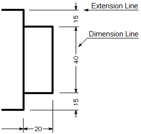
A technical drawing illustrating the use of extension lines and dimens (Source: 59d646f026634d9a)
- Assist in Layout: Help in positioning elements on the drawing sheet before finalizing the design.
- Separate Details: Provide a visual distinction between temporary guidelines and permanent outlines.
- Enable Modifications: Make it easier to erase or adjust parts of the drawing during the design process.
Characteristics of faint continuous lines
- Thickness: Thin lines typically between 0.18 mm and 0.25 mm.
- Lightness: Drawn lightly to avoid confusion with main outlines.
- Continuity: Lines are unbroken but subtle.
- Smoothness: Should be straight and steady to aid accuracy.
- Usage with Tools: Often drawn using a hard pencil (e.g., 2H) or fine technical pen.
Drawing faint continuous lines: procedure
- Select a hard pencil (2H) or a fine technical pen for light line work.
- Using a ruler or set square, lightly sketch the required guideline or dimension line.
- Ensure the line is straight and continuous without breaks.
- Draw extension lines from the object edges outward, leaving space for dimension figures.
- Add dimension lines parallel to the extension lines, placing arrowheads or ticks at ends.
- Write dimension figures clearly above or beside the dimension lines, ensuring legibility.
Importance of faint continuous lines in technical drawings
- Clarity in Measurements: They keep dimensions separate from object outlines, preventing confusion.
- Facilitate Accurate Drafting: Provide necessary guides for constructing precise drawings in schools and TVET colleges.
- Allow Easy Corrections: Lightness enables erasing without damaging the main drawing.
- Enhance Professionalism: Clean, faint lines contribute to neat, well-organized drawings.
- Support Communication: Help stakeholders like hotel managers understand sizes and placements without clutter.
Practice Questions
-
Explain why faint continuous lines are important for dimensioning in technical drawings used in cooperative business plans. (6 marks)
-
List and describe the characteristics of faint continuous lines and how they differ from boarder lines. (10 marks)
-
Describe the steps to draw faint continuous lines for dimensioning a rectangular farm plot of 50 m by 30 m. (8 marks)
2.1.3 Broken lines
Broken lines are dashed lines used to represent hidden edges and features not visible in the current view of a drawing. Organizations like retail businesses and banks use broken lines to communicate details such as concealed structural elements or internal components.
Purpose of broken lines
- Indicate Hidden Features: Show edges or details obscured behind visible surfaces.
- Represent Internal Structures: Illustrate components inside objects, such as wiring in a hotel electrical plan.
- Clarify Overlapping Parts: Help distinguish between visible and invisible parts in complex assemblies.
- Assist in Planning: Provide information needed for maintenance or installation without extra drawings.
- Standardize Communication: Maintain uniformity in representing hidden details across various sectors.
Characteristics of broken lines
- Pattern: Consist of short dashes, usually around 3 mm long, separated by equal spaces.
- Thickness: Medium thickness, typically 0.35 mm to 0.5 mm.
- Continuity: Dashed but evenly spaced.
- Visibility: Dark enough to be clear but not overpower main outlines.
- Placement: Drawn where hidden edges exist behind visible surfaces.
Drawing broken lines: procedure
- Identify hidden edges or features in the object or plan.
- Select a medium thickness technical pen or pencil for drawing.
- Using a ruler, mark the start and end points of the hidden feature line.
- Draw short dashes approximately 3 mm long, leaving equal gaps between each dash.
- Maintain consistent dash length and spacing throughout the line.
- Ensure the broken line aligns with the hidden edge’s position relative to visible features.
Importance of broken lines in professional drawings
- Reveal Concealed Details: Enable engineers and architects in county government offices to understand full structural layouts.
- Avoid Drawing Clutter: Show hidden features without adding separate sectional views.
- Assist Maintenance Teams: Provide information for repair work in hospitals or retail outlets.
- Standardize Drawings: Ensure consistent interpretation across multidisciplinary teams.
- Improve Accuracy: Help avoid construction errors by clearly indicating unseen components.
Practice Questions
-
Describe the function of broken lines in a technical drawing for a county hospital’s plumbing system. (6 marks)
-
Explain the characteristics and drawing procedure of broken lines used to show hidden features in a retail shop layout. (10 marks)
-
Outline how broken lines improve communication between architects and construction teams in a university building project. (6 marks)
2.1.4 Chain lines
Chain lines consist of alternating long and short dashes and are used to indicate centre lines, cutting planes, or special features in drawings. Kenyan professionals in sectors such as NEMA and cooperative societies rely on chain lines to differentiate critical elements like section cuts or boundaries.
Purpose of chain lines
- Mark Centre Lines: Identify axes of symmetry or rotation.
- Indicate Cutting Planes: Show where an object is cut for sectional views.
- Highlight Special Features: Denote important boundaries or limits.
- Distinguish from Other Lines: Separate chain lines from continuous or broken lines to avoid confusion.
- Support Detailed Analysis: Assist in understanding complex drawings in environmental reports or cooperative audits.
Characteristics of chain lines
- Pattern: Alternating long (about 6 mm) and short dashes (about 3 mm).
- Thickness: Medium thickness, similar to broken lines (0.35 mm to 0.5 mm).
- Continuity: Continuous alternating pattern without breaks.
- Visibility: Dark enough to stand out but not dominate the drawing.
- Placement: Positioned precisely according to the feature being marked.
Drawing chain lines: procedure
- Determine the feature to be marked (centre line, cutting plane, etc.).
- Select appropriate drawing tools such as a 0.5 mm technical pen.
- Using a ruler, draw a long dash approximately 6 mm.
- Follow with a short dash about 3 mm.
- Repeat the alternating pattern continuously along the required length.
- Ensure the line is straight and accurately positioned relative to the drawing elements.
Importance of chain lines in technical drawings
- Clarify Drawing Intent: Clearly shows where sections or symmetry exist in designs for banks or hotels.
- Aid in Interpretation: Helps users distinguish cutting planes from other line types.
- Enhance Accuracy: Ensures correct placement of sectional views in environmental impact drawings by NEMA.
- Improve Visual Hierarchy: Differentiates special features without cluttering the drawing.
- Facilitate Collaboration: Enables multidisciplinary teams to understand complex drawings easily.
Practice Questions
-
Explain the role of chain lines in marking cutting planes in a hotel floor plan. (6 marks)
-
Describe the characteristics and drawing steps of chain lines used in a cooperative society’s building layout. (10 marks)
-
Discuss how chain lines assist in interpreting sectional views in environmental reports prepared for NEMA. (6 marks)
2.1.5 Centre lines
Centre lines are thin lines made up of alternating long and short dashes, used to indicate the geometric centre of circles, arcs, or symmetrical objects. They are vital in organizations such as universities and SACCOs when producing accurate technical drawings of equipment or facilities.
Purpose of centre lines
- Identify Geometric Centres: Mark the centre point or axis of circles and arcs.
- Define Symmetry: Show symmetry axes in parts or assemblies.
- Aid in Measurement: Provide reference points for dimensioning and construction.
- Support Assembly Instructions: Help in locating holes, shafts, or features during manufacturing.
- Standardize Drawing Language: Ensure uniform understanding of centre positions across professional sectors.
Characteristics of centre lines
- Pattern: Alternating long and short dashes; long dashes about 6 mm, short about 3 mm.
- Thickness: Thin lines, usually 0.18 mm to 0.25 mm.
- Continuity: Continuous alternating pattern without breaks.
- Length: Lines extend beyond the feature edges to provide clear reference.
- Contrast: Light enough not to overpower object outlines but visible for reference.
Drawing centre lines: procedure
- Identify the centre of the circle or symmetrical object using compasses or measurement.
- Place the ruler or straight edge through the centre point for straight centre lines.
- Draw a long dash approximately 6 mm through the centre.
- Follow with a short dash about 3 mm.
- Continue the alternating pattern extending beyond the object edges.
- Repeat perpendicular centre lines if necessary to indicate multiple axes of symmetry.
Importance of centre lines in technical drawings
- Ensure Precision: Crucial for locating holes or features in equipment drawings for TVET college workshops.
- Facilitate Layout: Assist in planning symmetrical structures in county government office layouts.
- Enhance Clarity: Help avoid ambiguity in complex shapes by marking centres clearly.
- Support Manufacturing: Guide machining and assembly processes in cooperative business equipment.
- Maintain Standardization: Compliance with ISO and KEBS drawing conventions ensures drawings are understood universally.
Practice Questions
-
Describe the purpose and characteristics of centre lines in technical drawings for a university laboratory equipment layout. (6 marks)
-
Outline the procedure for drawing centre lines on a circular feature in a SACCO’s architectural plan. (10 marks)
-
Explain the significance of centre lines in ensuring accuracy during the assembly of mechanical parts in TVET workshops. (6 marks)
2.1.6 Cutting lines
Cutting lines indicate the location where an object is cut to produce a sectional view. These lines are essential in revealing internal features and details, commonly used in environmental impact plans or facility layouts for organizations such as NEMA and county referral hospitals.
Purpose of cutting lines
- Mark Section Locations: Show exactly where the object is sliced for sectional drawings.
- Reveal Internal Details: Allow visualization of hidden features within complex objects.
- Assist in Design Understanding: Provide clearer insight into construction or assembly.
- Support Quality Control: Enable inspection of internal parts in hospital equipment maintenance.
- Standardize Documentation: Ensure consistent presentation of sectional views across sectors.
Characteristics of cutting lines
- Pattern: Thick chain lines with alternating long and short dashes, often with arrowheads indicating the viewing direction.
- Thickness: Heavier than centre lines, typically 0.5 mm to 0.7 mm.
- Arrowheads: Placed at ends pointing towards the section view.
- Labeling: Cutting lines are often labeled with letters (e.g., A-A) to identify the section.
- Positioning: Drawn precisely where the cut occurs, aligned with the object features.
Drawing cutting lines: procedure
- Determine the section plane location on the object or plan.
- Use a technical pen of thickness 0.5 mm or more for drawing.
- Draw a continuous chain line with long and short dashes along the section plane.
- Add arrowheads at both ends, pointing in the direction of the view.
- Label the cutting line with capital letters to identify the section.
- Ensure the cutting line is clearly distinguishable from other lines on the drawing.
Importance of cutting lines in technical drawings
- Facilitate Detailed Visualization: Help engineers and planners in county referral hospitals understand internal layouts.
- Improve Communication: Provide clear instructions for construction or assembly teams.
- Enhance Accuracy: Reduce errors by clearly indicating where to view internal sections.
- Support Documentation: Essential for compliance with KEBS and ISO standards in technical reports.
- Aid in Training: Assist TVET students and trainees in comprehending complex designs.
Practice Questions
-
Explain the purpose and characteristics of cutting lines in technical drawings for an environmental project at NEMA. (6 marks)
-
Describe the step-by-step procedure for drawing cutting lines on a sectional plan of a county referral hospital. (10 marks)
-
Discuss the significance of cutting lines in improving the understanding of internal features in technical drawings. (6 marks)
The rest of this chapter
🔒Create a free account to open more of this chapter.
Free: practical guides, quick cards, workplace scenarios and more.
Create a free account 🔒2.2 Construction of angles
In the diverse workplaces across Kenya, from county government offices to retail businesses, accurate construction of angles is fundamental in producing precise technical drawings. Whether drafting floor plans for a hospital extension or designing layout schem…
🔒2.3 Bisection of angles
In various professional fields across Kenya, precise angle measurement and division are critical for accurate technical drawings. Whether designing a layout for a county government office, mapping agricultural plots, or preparing architectural plans for a hote…
🔒2.4 Measurement of angles
In Kenya’s diverse professional environments, precise measurement of angles is fundamental for technical drawing tasks across fields such as architecture, healthcare facility planning, business data visualization, and agricultural layout design. Understanding…
🔒2.5 Construction of plane geometric forms
In many Kenyan workplaces such as county government offices, hospitals, and retail businesses, the ability to accurately construct and interpret plane geometric forms is essential for creating technical drawings that communicate design ideas clearly. These geo…
🔒2.6 Construction of scales
In Kenyan professional settings, accurate measurement and representation of objects, buildings, or processes are essential across sectors such as county government planning offices, hospitals, educational institutions, and agricultural cooperatives. Scales ena…
Chapter Summary
This chapter focused on the essential elements of producing plane geometry drawings, beginning with the identification and purpose of different types of lines such as border lines, faint continuous lines, broken lines, chain lines, centre lines, and cutting lines. It then covered the step-by-step construction of various angles, including acute, right, reflex, obtuse, and straight angles, providing the foundation for accurate geometric shapes. The process of bisecting these angles was explored in detail to ensure precise division and symmetry. Measurement techniques for each angle type were also discussed to enable accurate verification during drawing. The chapter further addressed the construction of fundamental plane geometric forms such as triangles, quadrilaterals, polygons, and circles with tangents, emphasizing correct procedures and standards. Finally, it explained how to construct different types of scales including plane scales, diagonal scales, and scales for reducing or enlarging drawings, which are critical for maintaining proportional accuracy in technical drawings. Together, these topics equip learners with comprehensive skills to produce clear, precise, and standardized plane geometry drawings.
Self-Assessment
🔒 PDFDownload this self-assessment, with answers
A. Written Assessment
- What type of line is used to represent visible edges and outlines in technical drawings? (2 marks)
- Describe the purpose of a centre line in a plane geometry drawing. (2 marks)
🔒20 more in this section.
Chapter Examination Questions
🔒 PDFDownload these examination questions, with worked answers
SECTION A (40 Marks) - Answer ALL Questions
- Identify and describe the purpose of border lines in a technical drawing used for a county referral hospital project. (4 marks)
- Differentiate between centre lines and chain lines including their line styles and typical use in drawings for a university campus layout. (4 marks)
🔒18 more in this section.
Chapter Practical Activities
Practical 1: Draw a technical plane geometry drawing illustrating all standard line types
Welding Technology · Level 6
Technical Drawing
PRACTICAL ASSESSMENT
TIME: 4 HOURS
⬇ PDFCandidate Instructions (Candidate Tool)
Type: Individual
INSTRUCTIONS TO CANDIDATE:
1. You are required to perform the following task:
i. Produce an A3 technical plane geometry drawing 250 mm x 180 mm illustrating all standard line types with correct usage as per the provided working drawing.
2. You have been provided with the following resources for the practical task:
| Tools & Equipment | Materials |
|---|
| Drawing board | Drawing sheet A3 size |
| T-square | |
| Set squares (45° and 60°) | |
| Compass divider | |
| Pencils (2H, HB) | |
| Eraser | |
| Steel ruler | |
| French curves | |
⬇ PDFResources Required (Cutting List)
| S/N | Item | Quantity |
|---|
| 1 | Drawing board | 1 Pc per Candidate |
| 2 | T-square | 1 Pc per Candidate |
| 3 | Set squares (45° and 60°) | 1 set per Candidate |
| 4 | Compass divider | 1 Pc per Candidate |
| 5 | Pencils (2H, HB) | 2 Pcs per Candidate |
| 6 | Eraser | 1 Pc per Candidate |
| 7 | Steel ruler | 1 Pc per Candidate |
| 8 | French curves | 1 set per Candidate |
| 9 | Drawing sheet A3 size | 1 Pc per Candidate |
⬇ PDFAssessor Guide
| Items to be Evaluated | Marks Available | Marks Obtained | Comments |
|---|
| TASK 1: Safety and preparation |
Wore appropriate PPE (dustcoat or overall)
(Award 1 mark or 0) | 1 | | |
Set up drawing board and secured drawing sheet
(Award 1 mark or 0) | 1 | | |
Selected correct pencils and tools
(Award 1 mark or 0) | 1 | | |
| Sub-Total | 3 | | |
| TASK 2: Drawing execution |
Drew border lines as thick continuous lines
(Award 2 marks or 0) | 2 | | |
Drew faint continuous lines for dimension lines and projection lines
(Award 2 marks or 0) | 2 | | |
Drew broken lines for hidden features
(Award 2 marks or 0) | 2 | | |
Drew chain lines for center lines and cutting planes
(Award 2 marks or 0) | 2 | | |
Drew centre lines correctly with alternating long and short dashes
(Award 2 marks or 0) | 2 | | |
Used cutting lines appropriately with thick chain lines
(Award 2 marks or 0) | 2 | | |
| Sub-Total | 12 | | |
| TASK 3: Housekeeping |
Cleared drawing area and returned tools
(Award 1 mark or 0) | 1 | | |
Disposed of scrap paper correctly
(Award 1 mark or 0) | 1 | | |
| Sub-Total | 2 | | |
| PRODUCT CHECKLIST |
Border lines drawn with correct thickness and continuous
(Award 3 marks or 0) | 3 | | |
Faint continuous lines drawn correctly for dimension and projection lines
(Award 3 marks or 0) | 3 | | |
Broken lines for hidden edges correctly drawn
(Award 3 marks or 0) | 3 | | |
Chain lines correctly used for center and cutting lines
(Award 3 marks or 0) | 3 | | |
Centre lines correctly spaced and positioned
(Award 3 marks or 0) | 3 | | |
Cutting lines drawn with correct style and thickness
(Award 3 marks or 0) | 3 | | |
Overall drawing dimensions 250 mm x 180 mm ±1 mm tolerance
(Award 4 marks or 0) | 4 | | |
Drawing is neat, clean with no smudges or erasure marks
(Award 2 marks or 0) | 2 | | |
| Sub-Total | 24 | | |
| GRAND TOTAL | 41 | | |
ASSESSMENT OUTCOME: ☐ Competent ☐ Not Yet Competent (competent if at least 50%)
Practical 2: Construct Acute and Right Angles Using Compass and Ruler
Welding Technology · Level 6
Technical Drawing
PRACTICAL ASSESSMENT
TIME: 3 HOURS
⬇ PDFCandidate Instructions (Candidate Tool)
Type: Individual
INSTRUCTIONS TO CANDIDATE:
1. You are required to perform the following task:
i. Construct an acute angle of 45° and a right angle of 90° on A3 drawing paper using compass and ruler.
2. You have been provided with the following resources for the practical task:
| Tools & Equipment | Materials |
|---|
| Compass | Drawing paper A3 size |
| Ruler 300 mm steel scale | |
| Protractor 180 degrees | |
| Set square 45° and 60° | |
| Pencil HB | |
| Eraser | |
| Sharpener | |
⬇ PDFResources Required (Cutting List)
| S/N | Item | Quantity |
|---|
| 1 | Drawing paper A3 size | 1 sheet per Candidate |
| 2 | Compass | 1 per Candidate |
| 3 | Ruler 300 mm steel scale | 1 per Candidate |
| 4 | Protractor 180 degrees | 1 per Candidate |
| 5 | Pencil HB | 2 pcs per Candidate |
| 6 | Eraser | 1 per Candidate |
| 7 | Set square 45° and 60° | 1 set per Candidate |
| 8 | Sharpener | 1 per Candidate |
⬇ PDFAssessor Guide
| Items to be Evaluated | Marks Available | Marks Obtained | Comments |
|---|
| TASK 1: Safety and Preparation |
Wore appropriate PPE (e.g. dustcoat, closed shoes)
(Award 1 mark if PPE worn correctly, else 0) | 1 | | |
Prepared drawing sheet and instruments correctly
(Award 1 mark for neat and proper setup) | 1 | | |
Sharpened pencil appropriately before starting
(Award 1 mark if pencil is sharp and usable) | 1 | | |
| Sub-Total | 3 | | |
| TASK 2: Construction of Acute Angle (45°) |
Drew a baseline of 150 mm accurately
(Award 2 marks if baseline is within ±1 mm) | 2 | | |
Used compass to construct the 45° acute angle correctly
(Award 4 marks for correct arc and angle construction steps) | 4 | | |
Labeled the angle points clearly
(Award 1 mark for clear and correct labeling) | 1 | | |
| Sub-Total | 7 | | |
| TASK 3: Construction of Right Angle (90°) |
Used ruler and set square to draw a 150 mm baseline correctly
(Award 2 marks if baseline is within ±1 mm) | 2 | | |
Constructed 90° right angle using compass and ruler accurately
(Award 4 marks for precise and correct method) | 4 | | |
Labeled the right angle points clearly
(Award 1 mark for clear and correct labeling) | 1 | | |
| Sub-Total | 7 | | |
| TASK 4: Housekeeping |
Cleared work area leaving it tidy
(Award 1 mark for neat workplace after task) | 1 | | |
Returned all tools and unused materials to store
(Award 1 mark for proper tool/material return) | 1 | | |
Disposed of waste pencil shavings and eraser bits correctly
(Award 1 mark for correct waste disposal) | 1 | | |
| Sub-Total | 3 | | |
| PRODUCT CHECKLIST |
Acute angle constructed measures 45° ± 1°
(Award 5 marks if angle is within tolerance) | 5 | | |
Right angle constructed measures 90° ± 1°
(Award 5 marks if angle is within tolerance) | 5 | | |
Angles are neat, clean, and correctly labeled
(Award 3 marks for clarity and neatness) | 3 | | |
Baseline lengths for both angles are 150 mm ± 1 mm
(Award 4 marks if baseline lengths are within tolerance) | 4 | | |
| Sub-Total | 17 | | |
| GRAND TOTAL | 37 | | |
ASSESSMENT OUTCOME: ☐ Competent ☐ Not Yet Competent (competent if at least 50%)
🔒Construction of Obtuse and Reflex Angles Using Geometric ToolsPractical 3
🔒Construct and bisect various angles including straight anglesPractical 4
🔒Measure and Verify Angles Using ProtractorPractical 5
🔒Construct Triangles with Given DimensionsPractical 6
🔒Construct Quadrilaterals to Given SpecificationsPractical 7
🔒Construction of Regular Polygons with Specified SidesPractical 8
🔒Draw circles and tangents with precisionPractical 9
🔒Construct and use a plane scale for measurementPractical 10
🔒Construct and apply a diagonal scale 150 mm long with 1:20 ratioPractical 11
🔒Construct Reducing and Enlargement Scales and Convert MeasurementsPractical 12
🔒Draw a comprehensive plane geometry layout with multiple angle types and line stylesPractical 13
🔒Construction and Labelling of Cutting and Centre Lines on a Technical DrawingPractical 14
🔒Composite Geometric Drawing of Polygons with Inscribed Circles and TangentsPractical 15
