Orthographic drawings are fundamental in Kenya’s diverse professional fields for accurately representing three-dimensional objects on two-dimensional media, facilitating clear communication across departments and sectors. Whether in hospital equipment design, agricultural machinery maintenance, or business infrastructure layout, orthographic projections ensure all stakeholders understand component details without ambiguity. This chapter focuses on producing orthographic drawings using standard projection methods and correct dimensioning to meet Kenyan and international standards, essential skills for diploma-level TVET students.
3.1 Orthographic Drawings
Orthographic drawings translate complex components into multiple flat views, enabling precise visualization and measurement. In Kenya, professionals from healthcare to county government planning rely on these drawings to convey technical details clearly and uniformly. Understanding projection methods and their conventions is crucial for creating standardized drawings accepted in all sectors.
3.1.1 First Angle Projection
First angle projection is a method of orthographic projection commonly used internationally and recognized under ISO standards, including in Kenyan technical documentation. It involves projecting views onto planes located between the observer and the object, producing views arranged differently from third angle projection. This technique is especially prevalent in European and some African technical environments.
Principles of First Angle Projection
- Projection Plane Positioning: The object is placed in the first quadrant, meaning the projection plane lies between the observer and the object, causing images to be projected through the object onto the plane.
- View Arrangement: The top view is placed below the front view, the right side view is placed on the left side, and the left side view is placed on the right side of the front view.
- View Orientation: Each view is a direct orthogonal projection, meaning views show true dimensions without perspective distortion.
- Symbol Usage: The first angle projection symbol, standardized by BS EN ISO 5456-2, must appear in the title block for clarity.
- Application Context: Often used in sectors where ISO standards are dominant, such as county government infrastructure projects or hospital equipment design.
Step-by-Step Procedure for First Angle Projection Drawing
- Identify the Object: Examine the component to be drawn, noting its shape, features, and dimensions.
- Select Views: Choose principal views, front, top, and side, that best describe the object’s shape.
- Establish the Drawing Layout: Place the front view centrally on the drawing sheet.
- Project the Top View: Draw the top view directly below the front view, aligning edges vertically.
- Project the Side View: Draw the right side view to the left of the front view, aligning edges horizontally.
- Add Details and Hidden Lines: Include all necessary lines such as edges, holes, and hidden features using appropriate line types.
- Insert the First Angle Projection Symbol: Place the standard symbol in the title block or drawing corner.
- Review for Completeness: Verify all views align correctly and accurately represent the object.
Comparison with Third Angle Projection
- View Placement: First angle places the top view below the front; third angle places it above. Similarly, first angle puts the right side view on the left; third angle on the right.
- Standard Usage: First angle is ISO-preferred, common in Kenya’s international trade and government sectors; third angle is dominant in the USA and some private companies.
- Symbol Recognition: Each projection uses a distinct symbol, aiding in clear communication.
- Interpretation Ease: Users familiar with one method may misinterpret drawings in the other, necessitating clear labeling.
- Suitability: Selection depends on client or regulatory requirements; Kenyan SACCOs managing international equipment imports often specify projection method.
Common Mistakes in First Angle Projection
- Incorrect View Placement: Mixing positions of side and top views leads to confusion and errors.
- Omission of Projection Symbol: Without the symbol, viewers may misinterpret the projection method.
- Misalignment of Views: Views not properly aligned cause dimensional inaccuracies.
- Inconsistent Line Types: Using incorrect line weights or types reduces clarity.
- Neglecting Hidden Detail Lines: Omitting hidden lines hides important features, affecting manufacturing or maintenance.
3.1.2 Third Angle Projection
Third angle projection is widely used in Kenya’s manufacturing and construction industries, especially in firms trading with or adopting American standards. It involves projecting views onto planes behind the object relative to the observer, resulting in a different arrangement of views compared to first angle projection.
Principles of Third Angle Projection
- Projection Plane Positioning: The object lies in the third quadrant; the projection plane is behind the object from the observer’s perspective.
- View Arrangement: The top view is placed above the front view; the right side view is placed on the right side of the front view.
- View Orientation: Orthogonal views preserve true dimensions without perspective distortion.
- Use of Standard Symbol: The third angle projection symbol must be included for clarity, per BS EN ISO standards.
- Typical Industry Use: Common in Kenyan retail business product design and county government civil works drawings.
Step-by-Step Procedure for Third Angle Projection Drawing
- Analyze the Object: Understand the component’s geometry and features.
- Determine Principal Views: Select front, top, and side views that best reveal the object’s form.
- Prepare Drawing Sheet: Place the front view centrally on the sheet.
- Draw the Top View: Position the top view directly above the front view, aligning edges vertically.
- Draw the Side View: Place the right side view to the right of the front view, aligning edges horizontally.
- Add Details and Hidden Lines: Include all edges, holes, and internal features with appropriate line types.
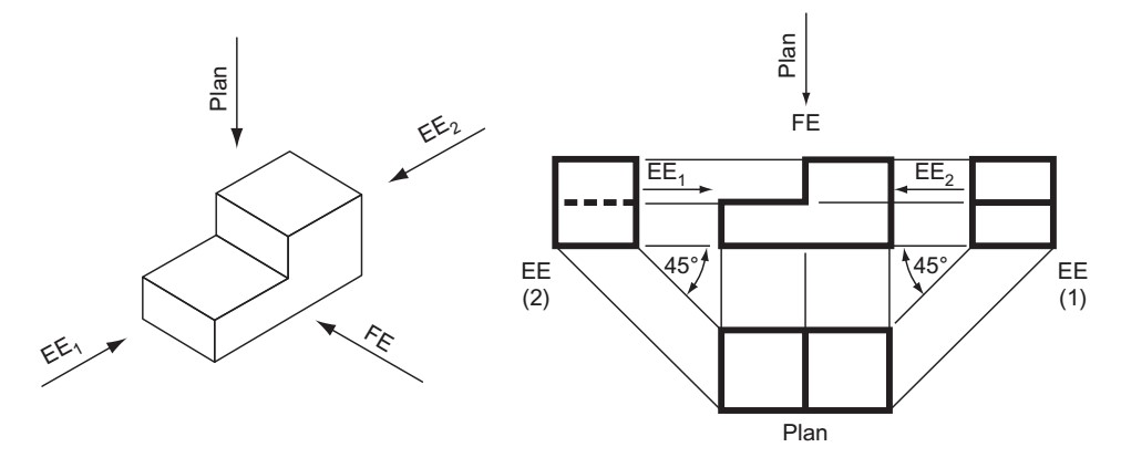
An isometric view and its corresponding orthographic projections (fron (Source: PLUMB 5 LEARNING GUIDE-1 (1))
- Insert Third Angle Projection Symbol: Place the symbol clearly on the drawing.
- Verify Accuracy and Completeness: Check alignment and details for correctness.
Advantages of Third Angle Projection in Kenyan Context
- Clarity for Local Manufacturing: Many Kenyan workshops and fabrication units are trained in third angle projection, easing communication.
- Compatibility with American Equipment: Kenyan hospitals and schools importing US-made equipment benefit from this method.
- Standardization: Facilitates uniformity in drawings across sectors using this projection.
- Ease of Interpretation: Logical placement of views corresponds to the object’s actual spatial orientation.
- Widely Taught: Most TVET colleges in Kenya emphasize third angle projection, supporting workforce readiness.
Challenges and Solutions in Third Angle Projection
Challenges
- Confusion with First Angle Projection: Learners often mix methods, producing incorrect views.
- Inconsistent Use of Symbols: Omitting or misplacing the projection symbol causes misinterpretation.
- Alignment Errors: Misaligned views lead to measurement and fabrication mistakes.
- Improper Line Types: Using incorrect line weights reduces drawing legibility.
- Inadequate Detailing: Failure to show hidden or sectional views limits drawing usefulness.
Solutions
- Clear Training on Differences: Emphasize distinctions between first and third angle in coursework.
- Mandatory Symbol Inclusion: Enforce symbol placement in all drawings.
- Use of Drawing Templates: Employ templates with predefined view positions to ensure alignment.
- Standardized Line Type Usage: Provide students with line type charts and enforce standards.
- Comprehensive Detailing Practices: Teach importance of hidden lines and sectional views for clarity.
Practice Questions
- Explain the difference in view placement between first angle and third angle projection. (5 marks)
- Describe the step-by-step procedure to construct a third angle orthographic drawing of a simple component. (10 marks)
- Identify five common errors made when producing first angle projection drawings and suggest how to avoid each. (10 marks)
- Given an object with specific dimensions, draw the front, top, and right side views using first angle projection. (15 marks)
The rest of this chapter
🔒Create a free account to open more of this chapter.
Free: practical guides, quick cards, workplace scenarios and more.
Create a free account 🔒3.2 Dimensioning
Dimensioning is critical in technical drawings to provide exact measurements required for manufacturing, construction, and maintenance. Accurate dimensioning ensures that components meet specifications, fit correctly, and function as intended across Kenya’s in…
🔒3.3 Sectional views
A sectional view shows the inside of an object by imagining that the object is cut by a plane and the part nearest the viewer is removed. Ordinary views show internal holes, recesses and cavities with hidden (dashed) lines, which become confusing when the inte…
🔒3.4 Free hand sketches
A free hand sketch is a drawing made without drafting instruments such as a T-square, compass or drawing board, using only a pencil, an eraser and the eye and hand of the person drawing. It is the fastest way to record and communicate an idea, a measurement or…
Chapter Summary
This chapter focused on producing orthographic drawings of components, beginning with an exploration of orthographic projection methods, specifically first angle and third angle projections, which are essential for accurately representing objects in two dimensions. It then detailed the principles of dimensioning, emphasizing the correct placement and clarity of measurements to ensure precise communication in technical drawings. The use of sectional views was covered to illustrate internal features of components that are not visible from the outside, enhancing the understanding of complex parts. The chapter also introduced free hand sketches as a valuable skill for quickly conveying ideas, starting with basic geometric forms and progressing to the use of appropriate tools and equipment. Finally, it discussed sketching mechanical components, highlighting the importance of accuracy and neatness for effective technical communication. Together, these topics provide a comprehensive foundation for creating clear, standardized, and informative technical drawings.
Self-Assessment
🔒 PDFDownload this self-assessment, with answers
A. Written Assessment
-
Which projection method places the object between the observer and the plane of projection?
a) First angle projection
b) Third angle projection
(2 marks)
-
Identify the correct position of the top view in first angle projection.
(2 marks)
🔒20 more in this section.
Chapter Examination Questions
🔒 PDFDownload these examination questions, with worked answers
SECTION A (40 Marks) - Answer ALL Questions
- Explain the difference between first angle projection and third angle projection using examples from a county hospital equipment layout. (4 marks)
- Identify the correct orthographic views needed to fully describe a rectangular storage box used in a retail shop. (4 marks)
🔒18 more in this section.
Chapter Practical Activities
Practical 1: Produce orthographic drawings of a mechanical component using first angle projection
Welding Technology · Level 6
Technical Drawing
PRACTICAL ASSESSMENT
TIME: 4 HOURS
⬇ PDFCandidate Instructions (Candidate Tool)
Type: Individual
INSTRUCTIONS TO CANDIDATE:
1. You are required to perform the following task:
i. Create orthographic drawings using first angle projection of a mechanical component 150 mm length × 100 mm width × 50 mm height as per the provided working drawing.
2. You have been provided with the following resources for the practical task:
| Tools & Equipment | Materials |
|---|
| Drawing board | Mechanical component working drawing sheet |
| T-square | |
| 45° set square | |
| Protractor | |
| Compass | |
| Divider | |
| Pencils (HB, 2H, 4H) | |
| Eraser | |
| Steel ruler (300 mm) | |
⬇ PDFResources Required (Cutting List)
| S/N | Item | Quantity |
|---|
| 1 | Drawing board | 1 Pc per Candidate |
| 2 | T-square | 1 Pc per Candidate |
| 3 | 45° set square | 1 Pc per Candidate |
| 4 | Protractor | 1 Pc per Candidate |
| 5 | Compass | 1 Pc per Candidate |
| 6 | Divider | 1 Pc per Candidate |
| 7 | Pencils (HB, 2H, 4H) | 1 Set per Candidate |
| 8 | Eraser | 1 Pc per Candidate |
| 9 | Mechanical component working drawing sheet | 1 Sheet per Candidate |
| 10 | Steel ruler (300 mm) | 1 Pc per Candidate |
⬇ PDFAssessor Guide
| Items to be Evaluated | Marks Available | Marks Obtained | Comments |
|---|
| TASK 1: Adherence to safety and preparation |
Candidate wears and uses PPE correctly (overall/dustcoat, safety boots, goggles)
(Award 1 mark for each correct PPE worn and used; total 3 marks) | 3 | | |
Candidate sets up drawing board and tools correctly
(Award 1 mark for proper setup of drawing board and 1 mark for correct arrangement of tools) | 2 | | |
| Sub-Total | 5 | | |
| TASK 2: Execution of orthographic drawing using first angle projection |
Candidate draws front view to scale with correct proportions
(Award 5 marks for accurate and neat front view matching dimensions) | 5 | | |
Candidate draws top view in correct first angle projection position
(Award 5 marks for correct placement and dimensioning of top view) | 5 | | |
Candidate draws side view in correct first angle projection position
(Award 5 marks for correct placement and dimensioning of side view) | 5 | | |
Candidate applies correct dimensioning and annotations as per standards
(Award 5 marks for legible, correct dimension lines and annotations) | 5 | | |
| Sub-Total | 20 | | |
| TASK 3: Housekeeping and submission |
Candidate cleans work area and returns tools properly
(Award 1 mark for cleaning, 1 mark for proper tool return, 1 mark for neat submission) | 3 | | |
| Sub-Total | 3 | | |
| PRODUCT CHECKLIST |
Orthographic drawing with front, top, and side views correctly drawn to scale and dimensioned: length 150 mm, width 100 mm, height 50 mm
(Award 5 marks each for correct front, top and side views with accurate dimensions) | 15 | | |
| Sub-Total | 15 | | |
| GRAND TOTAL | 43 | | |
ASSESSMENT OUTCOME: ☐ Competent ☐ Not Yet Competent (competent if at least 50%)
Practical 2: Produce Orthographic Third Angle Projection Drawing of a Mechanical Component
Welding Technology · Level 6
Technical Drawing
PRACTICAL ASSESSMENT
TIME: 4 HOURS
⬇ PDFCandidate Instructions (Candidate Tool)
Type: Individual
INSTRUCTIONS TO CANDIDATE:
1. You are required to perform the following task:
i. Produce orthographic third angle projection drawings of a mechanical component with overall dimensions 120 mm length, 80 mm width, and 40 mm height as per the provided working drawing.
2. You have been provided with the following resources for the practical task:
| Tools & Equipment | Materials |
|---|
| Drawing board | Tracing paper A3 size |
| T-square | |
| Set squares (45° and 60°) | |
| Drawing pencils (2H, HB, 2B) | |
| Eraser | |
| Compass | |
| Divider | |
| Steel ruler 300 mm | |
| Protractor | |
| French curves | |
| Tracing paper A3 size | |
⬇ PDFResources Required (Cutting List)
| S/N | Item | Quantity |
|---|
| 1 | Drawing board | 1 Pc per Candidate |
| 2 | T-square | 1 Pc per Candidate |
| 3 | Set squares (45° and 60°) | 1 set per Candidate |
| 4 | Drawing pencils (2H, HB, 2B) | 1 set per Candidate |
| 5 | Eraser | 1 Pc per Candidate |
| 6 | Compass | 1 Pc per Candidate |
| 7 | Divider | 1 Pc per Candidate |
| 8 | Steel ruler 300 mm | 1 Pc per Candidate |
| 9 | Protractor | 1 Pc per Candidate |
| 10 | French curves | 1 set per Candidate |
| 11 | Tracing paper A3 size | 5 sheets per Candidate |
| 12 | Mechanical component working drawing template | 1 Pc per Candidate |
⬇ PDFAssessor Guide
| Items to be Evaluated | Marks Available | Marks Obtained | Comments |
|---|
| TASK 1: Adherence to Safety and Preparation |
Wore appropriate PPE (overall, safety boots)
(Award 1 mark for each or zero x 2 = 2 Marks) | 2 | | |
Set up drawing board and tools correctly
(Award 2 marks or 0) | 2 | | |
Selected correct drawing instruments and materials
(Award 1 mark or 0) | 1 | | |
| Sub-Total | 5 | | |
| TASK 2: Drawing Execution |
Correctly laid out the three principal views using third angle projection
(Award 4 marks or 0) | 4 | | |
Accurately constructed views with correct proportions and scales
(Award 5 marks or 0) | 5 | | |
Used proper line types (visible, hidden, center lines) according to standards
(Award 3 marks or 0) | 3 | | |
Applied correct dimensioning with appropriate units and tolerance
(Award 4 marks or 0) | 4 | | |
| Sub-Total | 16 | | |
| TASK 3: Final Presentation and Clean-up |
Erased construction lines cleanly without smudging
(Award 2 marks or 0) | 2 | | |
Neatly annotated the drawing with title, scale, and projection symbol
(Award 2 marks or 0) | 2 | | |
Returned tools and cleaned the workstation
(Award 2 marks or 0) | 2 | | |
| Sub-Total | 6 | | |
| PRODUCT CHECKLIST |
Orthographic views dimensioned correctly: length 120 mm, width 80 mm, height 40 mm within ±1 mm tolerance
(Award 6 marks or 0) | 6 | | |
Views correctly placed according to third angle projection convention
(Award 4 marks or 0) | 4 | | |
Line types, scales, and annotations conform to standards
(Award 4 marks or 0) | 4 | | |
| Sub-Total | 14 | | |
| GRAND TOTAL | 41 | | |
ASSESSMENT OUTCOME: ☐ Competent ☐ Not Yet Competent (competent if at least 50%)
🔒Produce sectional views of a mechanical flange couplingPractical 3
🔒Freehand Sketching of Geometric FormsPractical 4
🔒Free hand orthographic sketches of mechanical componentsPractical 5
🔒Identify and demonstrate use of technical drawing tools for orthographic projectionPractical 6
🔒Dimension an Orthographic Drawing of a Mechanical ComponentPractical 7
🔒Produce Orthographic Drawings of an Assembled Mechanical ComponentPractical 8
🔒Draw orthographic projections of a truncated conePractical 9
🔒Produce free hand sectional views of a stepped shaftPractical 10
