Draft working drawings are essential in Tungsten Inert Gas (TIG) welding, guiding professionals through the precise fabrication of components. These drawings communicate detailed information about dimensions, tolerances, and welding symbols that ensure quality and accuracy in weld joints. Mastery of interpreting and creating these drawings is critical for welders, fabricators, and inspectors in Kenya’s manufacturing and construction industries to meet both client specifications and regulatory standards.
1.1 Drawing interpretation
Drawing interpretation forms the backbone of efficient welding projects. It involves understanding the graphical language used to convey the size, shape, and specifications of the welded component. For TIG welding professionals in Kenya, the ability to accurately interpret drawings reduces errors, minimizes waste, and ensures compliance with Kenyan Bureau of Standards (KEBS) and ISO welding documentation requirements.
1.1.1 Dimensions
Dimensions specify the exact measurements required to fabricate and assemble welded parts. Accurate dimension interpretation is crucial to achieving the desired fit and function of welded assemblies.
Types of dimensions
- Linear dimensions indicate straight-line distances between two points, essential for length, width, and height measurements.
- Angular dimensions specify the angle between two intersecting lines or surfaces, vital for components with inclined or beveled edges.
- Radial dimensions define the radius of curves or arcs, important in parts with circular features.
-
Diameter dimensions indicate the size of holes or cylindrical components.
-
Chain dimensions show a series of linear measurements added sequentially, useful for locating multiple features along a part.
Reading dimension lines and extension lines
- Dimension lines terminate with arrowheads pointing to extension lines, illustrating the exact points being measured.
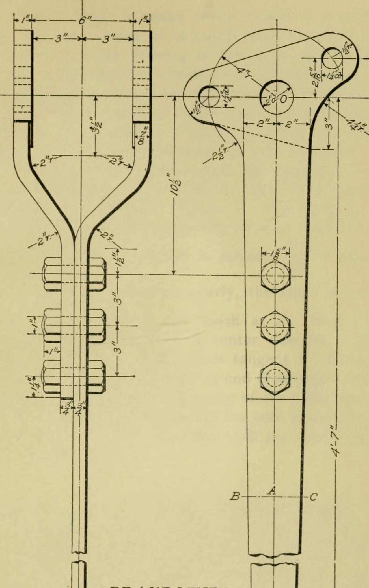
Engineering drawing with dimension lines shown (Source: Wikimedia Commons)
- Extension lines extend from the feature edges without touching them, indicating boundaries of the dimension.
- Units are typically in millimeters (mm) in Kenya, following BS EN ISO standards.
- Arrow styles vary but must be consistent within the drawing to avoid confusion.
- Placement of dimensions must avoid clutter and overlap with other drawing elements.
Importance of clear dimensioning
- Prevents fabrication errors by providing unambiguous measurements.
- Ensures correct material use, reducing wastage and costs.
- Facilitates quality control by enabling precise inspection.
- Supports effective communication among welders, engineers, and clients.
- Complies with Kenya Bureau of Standards and international welding codes.
Common dimensioning methods in welding drawings
- Baseline dimensioning uses a common reference line for multiple features, simplifying measurements.
- Chain dimensioning adds dimensions sequentially but risks cumulative errors.
- Coordinate dimensioning specifies features relative to a fixed origin point, preferred for complex parts.
1.1.2 Tolerances
Tolerances define permissible variations from specified dimensions, ensuring that parts fit and function correctly despite fabrication limits. In TIG welding, understanding tolerances is vital to maintain joint integrity and performance.
Meaning of tolerances
- Tolerance is the allowable deviation from a nominal dimension.
- It accounts for manufacturing variability and material behavior.
- Ensures interchangeability of parts produced in different batches.
- Supports functional requirements like strength and fit.
- Reduces rejection rates by defining acceptable quality limits.
Types of tolerances
- Limit tolerances specify maximum and minimum permissible sizes.
- Bilateral tolerances allow variation in both directions from the nominal size.
- Unilateral tolerances permit variation in only one direction.
- Geometric tolerances control shape, orientation, and position beyond size.
- Welding-specific tolerances address distortion and shrinkage from heat input.
Reading and applying tolerance symbols
- Tolerance values accompany dimensions, often in parentheses or as plus/minus figures.
- Geometric tolerances use frames with symbols indicating form, profile, orientation, location, and runout.
- Welders must interpret these to adjust techniques and joint preparation.
- Inspection personnel use tolerances to verify compliance.
- Kenyan standards align with ISO 2768 for general tolerances.
Impact of tolerances on TIG welding quality
- Tight tolerances demand precise control of weld bead size and placement.
- Excessive tolerance can lead to weak joints or misfits.
- Proper tolerance adherence ensures structural safety in construction and manufacturing.
- Welding procedures may be adjusted to meet tolerance requirements.
- Tolerance understanding reduces costly rework and delays.
1.1.3 Symbols and notations
Welding symbols and notations convey specific instructions about weld type, size, finish, and other requirements directly on drawings. Mastery of these symbols is indispensable for TIG welders in Kenya.
Basic welding symbols
- Arrow line points to the joint to be welded.
- Reference line carries symbols describing the weld.
- Tail includes additional notes or specifications.
- Fillet weld symbol looks like a triangle, indicating a fillet weld.
- Groove weld symbols depict different groove shapes such as V, U, J, etc.
Supplementary symbols
- Contour symbols specify weld surface finish: convex, concave, or flat.
- Weld-all-around symbol indicates continuous welding.
- Field weld symbol shows welding to be performed on site.
- Backing and spacer symbols specify additional materials used.
- Process symbols identify welding method, e.g., TIG, MIG.
Reading welding symbols on drawings
- Symbols are placed on the arrow side or opposite side of the reference line indicating weld location.
- Dimensions such as weld size are written adjacent to symbols.
- Additional instructions appear in the tail, including welding process, specifications, or inspection requirements.
- Kenyan welding codes align with AWS A2.4 and ISO 2553 standards.
- Welders must cross-reference symbols with procedure specifications.
Importance of standardized symbols
- Ensures clear communication across teams and stakeholders.
- Reduces misunderstandings that lead to welding defects.
- Facilitates training and competency assessment.
- Supports documentation and quality assurance processes.
- Harmonizes Kenyan welding practice with international norms.
1.1.4 Views/Elevations
Multiple views or elevations on a drawing represent the object from different angles to provide a complete understanding of its geometry. TIG welders use these views to visualize joint configurations and access points.
Orthographic projection views
- Front view shows the main face of the object.
- Top view displays the object as seen from above.
- Side views (left or right) provide additional perspectives.
- Views are arranged according to BS EN ISO 128 standards.
- Each view includes dimensions and welding symbols relevant to that side.
Auxiliary views
- Show inclined or oblique surfaces not clearly visible in principal views.
- Help clarify complex weld joint shapes.
- Important for detailing bevel angles and joint preparation.
- Often used in pipe fittings and structural components.
- Complement main views without duplicating information.
Sectional views
- Cut through the object to expose internal features.
- Essential for revealing hidden weld joints or internal geometry.
- Section lines indicate where the cut is made.
- Sectional views clarify weld penetration and fit-up.
- Support quality control by showing weld bead profiles.
Importance of multiple views
- Provide complete spatial understanding for accurate fabrication.
- Prevent misinterpretation of complex joints.
- Aid in planning welding sequence and accessibility.
- Facilitate communication between designer and welder.
- Ensure compliance with client specifications and standards.
1.1.5 Scale
Scale determines the proportional size of the drawing relative to the actual object. TIG welding drawings often require scaled representations to fit complex components on standard drawing sheets.
Meaning of scale
- Scale is the ratio of a drawing’s size to the real object’s size.
- Common scales include 1:1 (full size), 1:2 (half size), 2:1 (double size).
- Scale ensures large objects fit on manageable paper sizes.
- Enables detailed representation of small features.
- Must be clearly indicated on the drawing title block.
Types of scales used in welding drawings
- Full scale (1:1) for simple or small parts.
- Reduced scale (e.g., 1:5) for large components like frames or tanks.
- Enlarged scale (e.g., 5:1) to highlight small weld details.
- Architectural scales rarely used in welding but common in construction.
- Selection depends on complexity and size of the component.
Indicating and using scale
- Scale is noted in the title block or near the drawing views.
- Dimensions remain actual size regardless of scale.
- Scale helps inspectors relate drawing features to real parts.
- Scaling must be consistent across all views.
- Digital CAD drawings may use scalable vector graphics for accuracy.
Practical implications of scale in TIG welding
- Enables precise joint layout and fit-up.
- Assists in estimating material requirements.
- Supports training by providing clear visual references.
- Facilitates communication with clients and fabricators.
- Reduces errors from misinterpretation of size.
1.1.6 Measurement of angles
Angles are critical in TIG welding for bevel preparation, joint fit-up, and weld bead placement. Accurate angle measurement ensures correct weld penetration and joint strength.
Types of angles in welding
- Bevel angle is the angle of the prepared edge relative to the base metal surface.
- Included angle is the total angle between two beveled edges.
- Fillet weld angle relates to the leg dimensions of the weld.
- Chamfer angle refers to a beveled edge on the weld or base metal.
- Rotation angle in pipe welding defines the orientation of weld passes.
Tools for measuring angles
| Name |
Specification |
Use |
| Protractor |
Graduated 0° to 180°, plastic/metal |
Measuring and marking angles on flat surfaces |
| Bevel gauge |
Adjustable arm with locking mechanism |
Setting and transferring angles for bevels |
| Combination square |
Includes protractor and ruler |
Measuring angles and lengths simultaneously |
| Digital angle finder |
Electronic readout with high accuracy |
Precise angle measurement in degrees |
| Welding gauge |
Specially designed for weld fillet and bevel measurements |
Checking weld angles and leg lengths |
- Tools require calibration and proper handling.
- Clean surfaces ensure accurate angle reading.
- Digital tools improve measurement speed and accuracy.
- Bevel gauges assist in joint preparation.
- Welding gauges verify weld conformity to specifications.
Procedure for measuring bevel angles
- Clean the bevel surface to ensure no debris affects measurement.
- Place the bevel gauge’s adjustable arm along the beveled edge.
- Lock the arm in position to capture the angle.
- Read the angle directly from the protractor scale or digital display.
- Compare the measured angle to the specified drawing value.
- Adjust the bevel if necessary before welding.
Importance of precise angle measurement
- Ensures proper weld penetration and fusion.
- Prevents weak joints due to incorrect preparation.
- Facilitates consistent weld bead shape and size.
- Reduces the need for rework and repairs.
- Contributes to structural integrity and safety compliance.
1.1.7 Sketching of plane geometric forms
Sketching plane geometric forms helps welders visualize shapes and prepare for complex weld joints. It is a fundamental skill for communication and planning in TIG welding.
Basic plane geometric shapes
- Circle represents holes, pipes, or cylindrical parts.
- Square and rectangle depict plates or flat components.
- Triangle used in fillet weld profiles or gussets.
- Polygon shapes appear in flanges or brackets.
- Ellipse may represent angled holes or rounded features.
Techniques for sketching geometric forms
- Use ruler and compass for accuracy.
- Begin with light construction lines to establish proportions.
- Mark key dimensions clearly on sketches.
- Maintain correct orientation relative to the welding joint.
- Use shading or hatching to indicate material sections.
Importance of plane sketches in welding
- Facilitates communication between fabricators and designers.
- Helps plan welding sequence and joint access.
- Assists in estimating material quantities.
- Enables quick visualization of complex joints.
- Provides a basis for creating detailed working drawings.
Common challenges and solutions in sketching
- Difficulty maintaining proportions can be addressed by grid paper use.
- Misalignment of features corrected by careful measurement.
- Ambiguities reduced by annotating sketches with notes.
- Practice improves speed and accuracy.
- Use of templates and stencils aids consistency.
1.1.8 Solids sketches
Sketching solids presents three-dimensional views of components, essential for understanding complex weld joints and assemblies in TIG welding.
Types of solids commonly sketched
- Cubes and rectangular prisms for block components.
- Cylinders representing pipes and rods.
- Cones and pyramids for tapered parts.
- Spheres occasionally for rounded ends or fittings.
- Complex solids combining multiple shapes for assemblies.
Techniques for sketching solids
- Start with the basic geometric shape outline.
- Use isometric or perspective drawing methods to show depth.
- Draw construction lines lightly to guide shape proportions.
- Include visible and hidden edges with appropriate line types.
- Annotate sketches to clarify dimensions and weld locations.
Importance of solid sketches in TIG welding
- Provides spatial understanding for joint preparation.
- Aids in visualizing fit-up and access for welding.
- Supports communication with engineers and clients.
- Helps identify potential interference or alignment issues.
- Facilitates fabrication planning and sequencing.
Common difficulties and remedial practices
- Visualizing depth can be challenging; use step-by-step layering.
- Maintaining scale requires careful measurement.
- Differentiating visible and hidden edges by line weight.
- Practice with real objects improves skill.
- Use of CAD software complements manual sketching.
1.1.8.4 Cuboids Cylinders
Practice Questions
- Explain the different types of dimensions used in welding drawings and their significance. (10 marks)
- Describe how tolerances affect the quality of TIG welds and list four types of tolerances commonly used. (10 marks)
- Identify and interpret the basic welding symbols used in TIG welding drawings. (10 marks)
- Explain the purpose of multiple views in technical drawings and describe the difference between orthographic and sectional views. (10 marks)
- Define scale in technical drawings and explain how it influences the drawing and fabrication process. (10 marks)
- Outline the steps for measuring bevel angles and explain why accurate angle measurement is important in TIG welding. (10 marks)
- Describe the techniques for sketching plane geometric forms and their role in welding preparation. (10 marks)
- Discuss the importance of solids sketches and the methods used to represent three-dimensional objects in welding drawings. (10 marks)
The rest of this chapter
🔒Create a free account to open more of this chapter.
Free: practical guides, quick cards, workplace scenarios and more.
Create a free account 🔒1.2 Draft work drawings
Draft work drawings are essential in tungsten inert gas (TIG) welding because they communicate precise details about weld joints, dimensions, and specifications. In Kenya’s welding workshops and fabrication industries, these drawings ensure welders produce con…
🔒1.3 Operation procedure
Operation procedures in TIG welding detail the step-by-step process to produce the weld, ensuring consistency, safety, and quality. Kenyan welding fabricators and workshops rely on standardized procedures to train welders, maintain quality control, and meet cl…
Chapter Summary
This chapter provided a comprehensive overview of draft working drawings essential for Tungsten Inert Gas welding. It began with drawing interpretation, covering how to read and apply linear and angular dimensions, understand tolerances, and recognize standard symbols and notations. The chapter explained different views and elevations, focusing on first angle and third angle projections, as well as the importance of scale and accurate measurement of angles. It then guided students through sketching various plane geometric forms such as triangles, quadrilaterals, polygons, circles, and tangents, before advancing to solid sketches including prisms, cones, cubes, cuboids, and cylinders. The section on draft work drawings emphasized correct dimensioning and the use of welding symbols and notations to communicate welding requirements clearly. Finally, the chapter discussed the operation procedure for developing and using these drawings in practical welding contexts to ensure precision and quality in fabrication.
Self-Assessment
🔒 PDFDownload this self-assessment, with answers
A. Written Assessment
- What is the difference between first angle and third angle projection in technical drawings? (3 marks)
- Identify three common welding symbols used in TIG welding drawings and briefly describe their meaning. (3 marks)
🔒20 more in this section.
Chapter Examination Questions
🔒 PDFDownload these examination questions, with worked answers
SECTION A (40 Marks) - Answer ALL Questions
- Explain the importance of linear dimensions on a TIG welding working drawing for a structural steel frame used in a Nairobi hotel (4 marks)
- Differentiate between first angle and third angle projection views in welding drawings (4 marks)
🔒28 more in this section.
Chapter Practical Activities
Practical 1: Interpretation of Tungsten Inert Gas Welding Working Drawing
Welding · Level 4
Tungsten Inert Gas Welding
PRACTICAL ASSESSMENT
TIME: 4 HOURS
⬇ PDFCandidate Instructions (Candidate Tool)
Type: Individual
INSTRUCTIONS TO CANDIDATE:
1. You are required to perform the following task:
i. Interpret the provided TIG welding working drawing detailing weld types, symbols, and notations for a steel assembly measuring 200mm x 150mm x 50mm.
2. You have been provided with the following resources for the practical task:
| Tools & Equipment | Materials |
|---|
| Pencil and eraser | Welding working drawing sheet A3 size |
| Ruler 300 mm | Set of welding symbols reference charts |
⬇ PDFResources Required (Cutting List)
| S/N | Item | Quantity |
|---|
| 1 | Welding working drawing sheet A3 size | 1 Pc per Candidate |
| 2 | Set of welding symbols reference charts | 1 Set per Candidate |
| 3 | Pencil and eraser | 1 Set per Candidate |
| 4 | Ruler 300 mm | 1 Pc per Candidate |
⬇ PDFAssessor Guide
| Items to be Evaluated | Marks Available | Marks Obtained | Comments |
|---|
| TASK 1: Interpretation of welding symbols and notations |
Wore PPE correctly: welding shield, safety boots, leather gloves, leather apron
(Award 1 mark for each correctly worn PPE item) | 4 | | |
Identified and correctly interpreted weld type symbols on the drawing
(Award 1 mark for each correctly identified weld symbol, total 5 symbols) | 5 | | |
Correctly interpreted welding process notations and parameters
(Award 1 mark for each correct notation interpretation) | 3 | | |
Accurately noted weld size and length dimensions from the drawing
(Award 1 mark for each correct dimension interpretation) | 3 | | |
Correctly identified welding positions as per the drawing
(Award 1 mark for each correctly identified welding position) | 3 | | |
| Sub-Total | 18 | | |
| PRODUCT CHECKLIST |
Accurate interpretation of weld symbols and annotations matching the drawing
(Award 2 marks for each correctly interpreted weld symbol and corresponding notation, total 5 symbols) | 10 | | |
Correct extraction of weld size and length dimensions (200mm x 150mm x 50mm)
(Award 1 mark for each correctly noted dimension) | 5 | | |
| Sub-Total | 15 | | |
| GRAND TOTAL | 33 | | |
ASSESSMENT OUTCOME: ☐ Competent ☐ Not Yet Competent (competent if at least 50%)
Practical 2: Application of Linear and Angular Dimensions on a TIG Welding Layout
Welding · Level 4
Tungsten Inert Gas Welding
PRACTICAL ASSESSMENT
TIME: 4 HOURS
⬇ PDFCandidate Instructions (Candidate Tool)
Type: Individual
INSTRUCTIONS TO CANDIDATE:
1. You are required to perform the following task:
i. Prepare a working drawing applying linear and angular dimensions for a TIG welded bracket measuring 150 mm length, 100 mm width with a 45° angled gusset as per the provided layout.
2. You have been provided with the following resources for the practical task:
| Tools & Equipment | Materials |
|---|
| Drawing board | Working drawing paper A3 size |
| T-square | |
| Protractor 180° | |
| Set squares (45° and 60°) | |
| Steel ruler 300 mm | |
| Pencil HB | |
| Eraser | |
⬇ PDFResources Required (Cutting List)
| S/N | Item | Quantity |
|---|
| 1 | Drawing board | 1 Pc per Candidate |
| 2 | T-square | 1 Pc per Candidate |
| 3 | Protractor 180° | 1 Pc per Candidate |
| 4 | Set squares (45° and 60°) | 1 Set per Candidate |
| 5 | Steel ruler 300 mm | 1 Pc per Candidate |
| 6 | Pencil HB | 2 Pcs per Candidate |
| 7 | Eraser | 1 Pc per Candidate |
| 8 | Working drawing paper A3 size | 1 Sheet per Candidate |
⬇ PDFAssessor Guide
| Items to be Evaluated | Marks Available | Marks Obtained | Comments |
|---|
| TASK 1: Preparation and Setup |
Wore PPE correctly including eye protection and dust coat
(Award 1 mark for each PPE worn correctly) | 2 | | |
Set up drawing board with paper securely fixed
(Award 1 mark for correct setup) | 1 | | |
Selected and arranged drawing tools appropriately
(Award 1 mark for proper tool selection and arrangement) | 1 | | |
| Sub-Total | 4 | | |
| TASK 2: Application of Linear Dimensions |
Measured and marked 150 mm length accurately
(Award 2 marks for correct measurement and marking) | 2 | | |
Measured and marked 100 mm width accurately
(Award 2 marks for correct measurement and marking) | 2 | | |
Applied linear dimension lines with proper arrows and text clarity
(Award 2 marks for neat and correct dimensioning) | 2 | | |
| Sub-Total | 6 | | |
| TASK 3: Application of Angular Dimensions |
Measured and marked 45° angle on gusset using protractor
(Award 3 marks for accurate angle measurement and marking) | 3 | | |
Applied angular dimension with correct symbol and notation
(Award 2 marks for correct angular dimensioning) | 2 | | |
| Sub-Total | 5 | | |
| TASK 4: Final Drawing Presentation |
Erased construction lines cleanly without damaging drawing
(Award 2 marks for neatness and cleanup) | 2 | | |
Checked and corrected any dimensioning errors
(Award 2 marks for thorough checking and correction) | 2 | | |
| Sub-Total | 4 | | |
| PRODUCT CHECKLIST |
Working drawing shows linear dimensions: 150 mm length and 100 mm width within ±1 mm tolerance
(Award 3 marks for accurate linear dimensions) | 3 | | |
Angular dimension of 45° applied correctly within ±1° tolerance
(Award 3 marks for accurate angular dimension) | 3 | | |
Dimension lines, arrows, and text conform to drafting standards and are legible
(Award 2 marks for proper dimensioning conventions and legibility) | 2 | | |
Drawing is neat, clean, and free of smudges or unnecessary marks
(Award 2 marks for overall presentation quality) | 2 | | |
| Sub-Total | 10 | | |
| GRAND TOTAL | 29 | | |
ASSESSMENT OUTCOME: ☐ Competent ☐ Not Yet Competent (competent if at least 50%)
🔒Application of Dimensional Tolerances on a TIG Welded BracketPractical 3
🔒Draw first angle projection views and elevations of a TIG welded componentPractical 4
🔒Draft third angle projection views and elevations for TIG welding componentPractical 5
🔒Scaling a Working Drawing of a Steel Frame SectionPractical 6
🔒Sketching Plane Geometric Forms: Triangles and QuadrilateralsPractical 7
🔒Sketching polygons and circles with tangents for TIG welding layoutPractical 8
🔒Sketching Solid Geometric Forms: Prisms and ConesPractical 9
🔒Sketching Solid Geometric Forms: Cubes, Cylinders, and CuboidsPractical 10
🔒Draft a complete working drawing for TIG welding fabricationPractical 11
🔒Application of Welding Symbols and Notations on a 200mm x 150mm TIG Welded Lap Joint DrawingPractical 12
🔒Draft a Step-by-Step Welding Operation Procedure for a TIG Welded Butt JointPractical 13
🔒Development and Layout of Welding Component Patterns for TIG WeldingPractical 14
🔒Fabricate TIG welded rectangular frame as per working drawingPractical 15
