
By the end of this chapter, you will be able to:
Mastering these skills ensures you create clear, precise fire control system drawings that help keep buildings safe and protect lives.
Compiled by: Elijah Kiprono
Fire control systems are critical components in plumbing installations within Kenyan buildings, ensuring safety by managing fire risks through early detection, suppression, and containment. Preparing accurate schematic drawings for these systems is an essential skill for plumbing professionals, as it guides installation, maintenance, and compliance with regulatory standards. This chapter equips learners with the foundational terminology and concepts necessary to design and interpret fire control system schematics effectively.
The foundation of preparing fire control system schematic drawings lies in understanding the key terms and concepts used throughout the design and implementation process. In the Kenyan plumbing context, these terms ensure clear communication among designers, installers, and regulatory bodies such as the National Construction Authority and the Fire Risk Reduction Committees. Mastery of these terms facilitates compliance with Kenya Building Code and enhances safety outcomes in various sectors including hospitals, schools, and county government offices.
Fire detection devices are integral to fire control systems, providing the initial alert to the presence of fire hazards. Kenyan plumbing professionals must understand these devices to integrate them effectively within water-based fire suppression systems such as sprinklers.
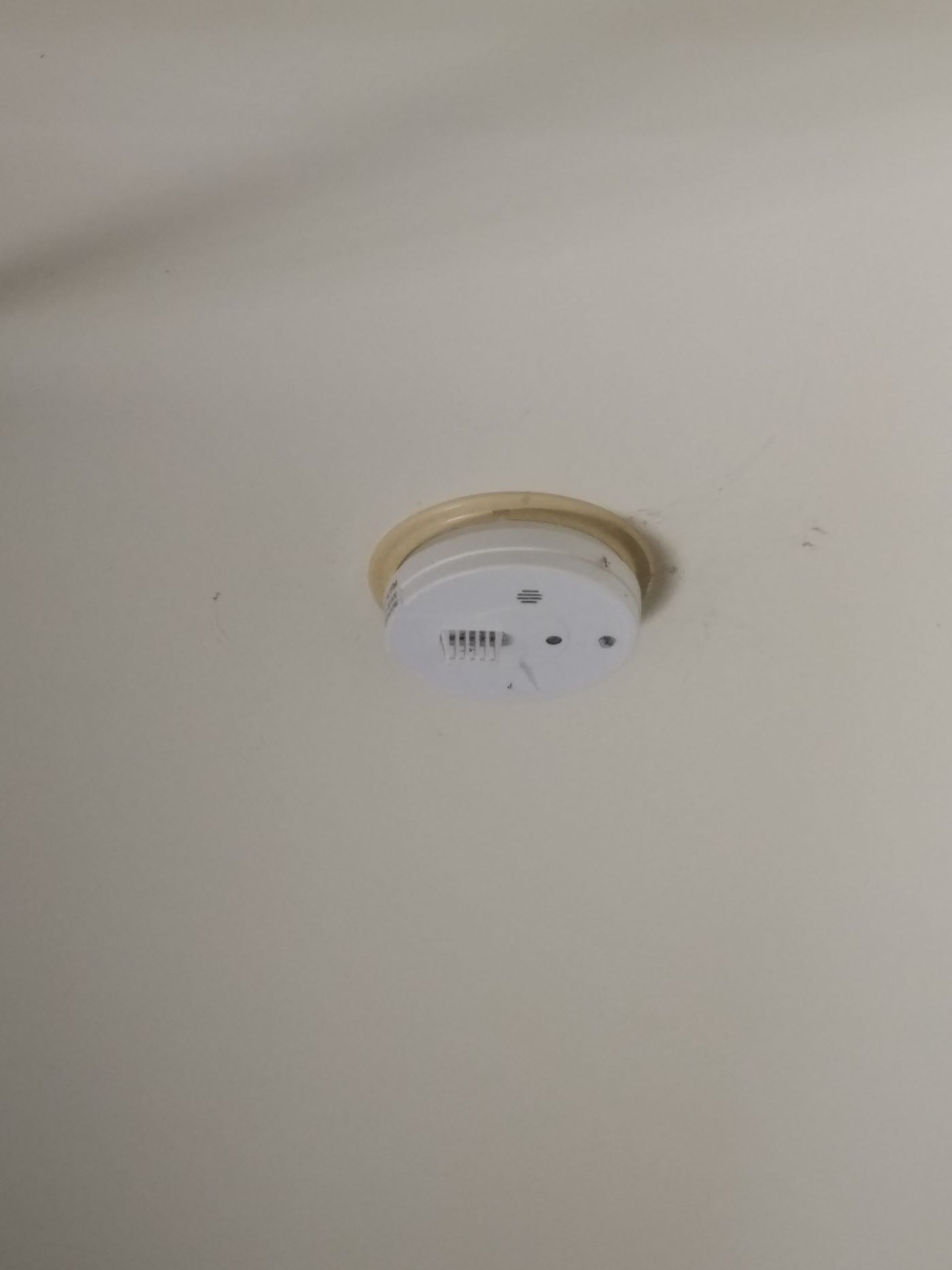
Ceiling-mounted heat detector device (Source: Wikipedia (Heat detector))
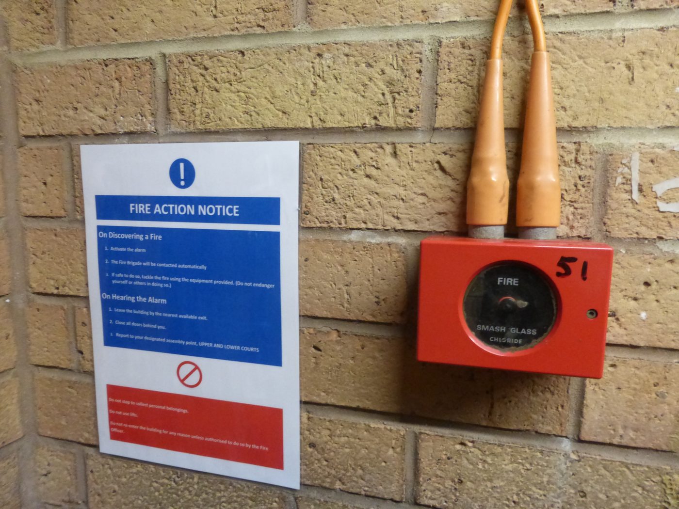
Red manual call point on wall with fire action notice (Source: Wikimedia Commons)
Understanding fire suppression systems is vital for plumbing professionals tasked with designing water-based fire control schematics. These systems actively control or extinguish fires once detected.
A fire suppression system layout in a building (Source: fire_control (1))
Sprinkler Systems automatically discharge water through piping networks when heat triggers activation, common in commercial buildings.
Hydrant Systems provide accessible water outlets for firefighting personnel, essential in retail businesses and large institutions.
A schematic drawing must detail all components making up the fire control system, ensuring clarity for installation and maintenance.
A fire alarm system layout (Source: fire_control (1))
Alarm Devices include sirens and strobe lights alerting occupants, critical in densely populated areas such as universities.
Water Supply Sources such as tanks or mains connections must be clearly indicated, with capacity considerations reflecting building size.
Compliance with national and international standards is mandatory for fire control system schematics, ensuring safety and legal adherence in Kenya.
Define and explain the function of at least three types of fire detection devices used in plumbing fire control systems. (10 marks)
List and describe five components that must be included in a fire control system schematic drawing for a commercial building. (10 marks)
Identify and explain the importance of two key standards or codes that influence fire control system design in Kenya. (10 marks)
Describe the differences between sprinkler and deluge fire suppression systems, including typical applications for each. (10 marks)
Create a free account to open more of this chapter.
Free: practical guides, quick cards, workplace scenarios and more.
Create a free accountThis chapter introduced key terms and concepts essential for understanding fire control systems, providing a foundation for accurate schematic drawing. It emphasized the importance of personal protective equipment to ensure safety while working on fire control installations. The use of working drawings was explained as a critical step for planning and executing fire control system layouts. Essential drawing instruments were outlined to equip learners with the tools needed for precise drafting. The chapter also covered measurement conversions to enable accurate scaling and dimensioning of drawings. Standard symbols used in fire control system schematics were presented to ensure clarity and uniformity in communication. Finally, the chapter guided students through the process of sketching fire control systems, combining all previous elements into coherent and professional schematic drawings.
Type: Individual
| Tools & Equipment | Materials |
|---|---|
| Drawing board | Tracing paper A3 size |
| T-square ruler | Fire control system symbol chart |
| Set squares | |
| Technical drawing pencils | |
| Eraser | |
| Sharpener | |
| Tracing paper | |
| Scale ruler | |
| Drafting compass |
| S/N | Item | Quantity |
|---|---|---|
| 1 | Fire control system symbol chart | 1 set per Candidate |
| 2 | Drawing board | 1 Pc per Candidate |
| 3 | T-square ruler | 1 Pc per Candidate |
| 4 | Set squares (45° and 60°) | 1 set per Candidate |
| 5 | Technical drawing pencils (2H, HB, 2B) | 1 set per Candidate |
| 6 | Eraser and sharpener | 1 set per Candidate |
| 7 | Tracing paper A3 size | 2 sheets per Candidate |
| 8 | Scale ruler (metric) | 1 Pc per Candidate |
| 9 | Drafting compass | 1 Pc per Candidate |
| 10 | Personal Protective Equipment (overall, gloves, safety boots) | 1 set per Candidate |
| Items to be Evaluated | Marks Available | Marks Obtained | Comments |
|---|---|---|---|
| TASK 1: Identification and application of fire control system symbols | |||
| Used personal protective equipment (overall, gloves, safety boots) (Award 1 mark for each PPE worn or zero = 3 marks) | 3 | ||
| Selected correct drawing tools and materials for the task (Award 1 mark each for correctly selected tools and materials or zero = 3 marks) | 3 | ||
| Accurately set out the schematic drawing area to 1200mm by 900mm (Award 4 marks for correct layout dimensions or zero) | 4 | ||
| Correctly identified and applied at least 10 standard fire control system symbols as per the symbol chart (Award 1 mark for each correct symbol applied or zero) | 10 | ||
| Maintained neatness and clarity in symbol drawing and labelling (Award 3 marks for clear and neat drawing or zero) | 3 | ||
| Used appropriate line types and weights for different components (Award 3 marks for correct line usage or zero) | 3 | ||
| Sub-Total | 26 | ||
| PRODUCT CHECKLIST | |||
| Schematic drawing area dimensioned correctly (1200mm x 900mm) within ±2mm tolerance (Award 4 marks for correct dimensions or zero) | 4 | ||
| All applied symbols match standard fire control system symbols and are correctly oriented (Award 6 marks for correct symbols matching standards or zero) | 6 | ||
| Drawing is complete, with all required symbols included and properly labelled (Award 4 marks for completeness or zero) | 4 | ||
| Drawing is neat, legible, and professionally presented (Award 4 marks for overall presentation or zero) | 4 | ||
| Sub-Total | 18 | ||
| GRAND TOTAL | 44 | ||
Type: Individual
| Tools & Equipment | Materials |
|---|---|
| Pipe wrench | GI Pipes |
| Pipe cutter | Gate valve |
| Pipe threading equipment | GI Tee |
| Measuring tape | GI Elbow |
| Drawing instruments | Fire sprinkler |
| Water tank | |
| GI Back nut | |
| GI Long nipple | |
| Fire pump | |
| Teflon tape | |
| Non-return valve | |
| Nipple | |
| Union |
| S/N | Item | Quantity |
|---|---|---|
| 1 | 19mm diameter GI Pipe | 2 M per Candidate |
| 2 | 19mm diameter Gate valve | 1 Pc per Candidate |
| 3 | 19mm diameter GI Tee | 1 Pc per Candidate |
| 4 | 19mm diameter GI Elbow | 4 Pcs per Candidate |
| 5 | Fire sprinkler | 2 Pcs per Candidate |
| 6 | Water tank | 1 Pc per Candidate |
| 7 | 19mm diameter GI Back nut | 2 Pcs per Candidate |
| 8 | 19mm diameter GI Long nipple | 1 Pc per Candidate |
| 9 | Fire pump (pump booster) | 1 Set per Candidate |
| 10 | Teflon tape | Sufficient per Candidate |
| 11 | Non-return valve | 1 Pc per Candidate |
| 12 | Nipple | 2 Pcs per Candidate |
| 13 | Union | 2 Pcs per Candidate |
| 14 | Personal Protective Equipment (Gloves, Overall, Industrial boots) | Full gear per Candidate |
| Items to be Evaluated | Marks Available | Marks Obtained | Comments |
|---|---|---|---|
| TASK 1: Preparation and Assembly | |||
| Used personal protective equipment (Gloves, Overall, Industrial boots) (Award 1 mark for each PPE item worn or zero = 3 marks) | 3 | ||
| Cut pipes properly to accurate measurements without visible damage or cracks (Award 2 marks or zero) | 2 | ||
| Connected fittings securely to pipes (Gate valve, Non-return valve) (Award 1 mark for each fitting connected securely or zero) | 4 | ||
| Installed fire pump booster properly and powered (Award 3 marks or zero) | 3 | ||
| Positioned water tank correctly (Award 2 marks or zero) | 2 | ||
| Connected pipes properly to water supply and fire sprinklers (Award 1 mark for each correct connection or zero) | 4 | ||
| Installed fire sprinkler system correctly (Award 4 marks or zero) | 4 | ||
| Used piping tools and equipment correctly (Pipe wrench, Pipe threading equipment, Pipe cutter) (Award 1 mark for each tool used correctly or zero) | 3 | ||
| Proper disposal of waste materials after task completion (Award 2 marks or zero) | 2 | ||
| Sub-Total | 27 | ||
| PRODUCT CHECKLIST | |||
| Schematic sketch with accurate dimensions: length 600 mm and width 400 mm (+/- 2 mm tolerance) (Award 4 marks for correct dimensions or zero) | 4 | ||
| Schematic shows all key components (fire pump, water tank, gate valve, sprinklers, pipes) correctly positioned and labeled (Award 3 marks for completeness or zero) | 3 | ||
| Drawing is neat, clear, and correctly annotated (Award 3 marks for neatness and clarity or zero) | 3 | ||
| Sub-Total | 10 | ||
| GRAND TOTAL | 37 | ||
At the start of this chapter we promised you would be able to:
Tick each one you can genuinely do.
So, are you there yet?
You're competent when you can confidently do 50% or more of what this chapter promised.
Sign in to record how you're doing.