Interpretation of drainage system drawings is a critical skill for plumbing professionals in Kenya, ensuring installations meet local standards and function efficiently. This chapter introduces various types of working drawings used in domestic drainage system projects, focusing on their characteristics and applications. Mastery of these drawings enables plumbers to translate design intent into practical installation, reducing errors and rework on site.
3.1 Working drawings
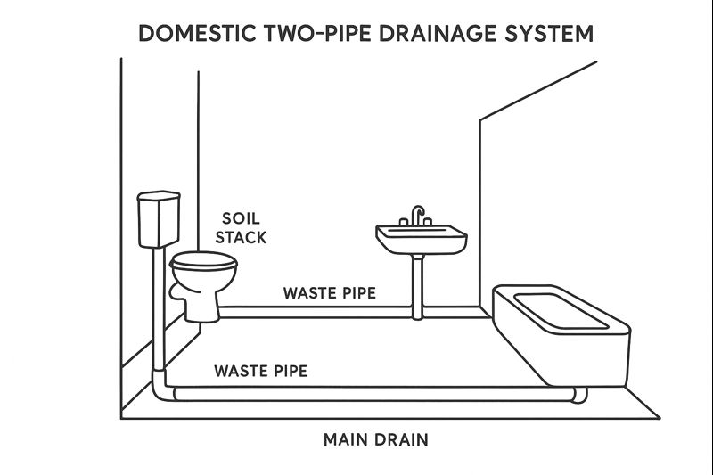
A domestic two-pipe drainage system (Source: drainage 2 checklist mod 2)
3.1.1 Pictorial drawings
Pictorial drawings present three-dimensional views of drainage systems, helping plumbers visualize the arrangement of pipes and fixtures in space.
Purpose of pictorial drawings
- Visual representation: They provide a realistic image of how components fit together, aiding comprehension beyond flat diagrams.
- Communication tool: Useful for explaining system layout to clients or non-technical stakeholders.
- Spatial awareness: Help identify potential clashes or access issues before installation.
- Training aid: Serve as educational tools for apprentices and trainees learning system configurations.
- Project coordination: Facilitate discussions among multidisciplinary teams by showing a common visual reference.
Characteristics of pictorial drawings
- Three-dimensional appearance: Objects are depicted with depth, height, and width.
- Use of perspective or isometric views: Commonly employ isometric projections to maintain scale along all axes.
- Detail level: May include pipe diameters, joint types, and fixture shapes.
- Color coding: Pipes and fittings can be color-coded to distinguish materials or functions.
- Annotations: Often include labels or legends clarifying components and flow directions.
Interpretation techniques for pictorial drawings
- Identify key components: Locate main drains, vents, and fixtures first.
- Follow flow paths: Trace the drainage route from fixtures to discharge points.
- Note elevations: Observe vertical relationships to ensure proper slopes.
- Check connections: Confirm how pipes join and transition.
- Relate to site conditions: Visualize how the drawing corresponds to actual spaces.
Limitations of pictorial drawings
- Scale ambiguity: Not always drawn to scale, which can mislead dimensioning.
- Complexity for large systems: May become cluttered and hard to interpret.
- Lack of detailed measurements: Precise lengths and slopes are often omitted.
- Not suitable for fabrication: Cannot replace detailed working drawings needed for construction.
- Requires familiarity: Novices may find 3D views confusing without prior experience.
3.1.2 Line drawings
Line drawings are schematic representations using lines and symbols to depict drainage systems in two dimensions.
Definition and purpose of line drawings
- Simplified representation: Show layout and connections without 3D detail.
- Technical communication: Provide precise information on pipe routing and sizes.
- Design documentation: Used for submission to regulatory bodies and approvals.
- Field reference: Guide plumbers during installation and troubleshooting.
- Cost estimation: Assist quantity surveyors in calculating material needs.
Types of line drawings in plumbing
Standards and conventions for line drawings
- Line types: Continuous lines for visible edges, dashed lines for hidden elements.
- Symbols: Use of standardized plumbing symbols as per BS EN ISO 4064 and KEBS guidelines.
- Dimensioning: Clear indication of pipe diameters, lengths, and slope gradients.
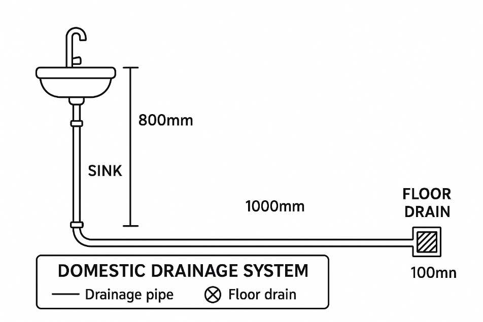
A domestic drainage system (Source: drainage 1 tool mod 1)
- Notes and legends: Provide explanations for symbols and special instructions.
- Title blocks: Include project details, drawing scale, author, and date.
Reading and interpreting line drawings
- Locate key nodes: Identify main stack, inspection chambers, and discharge points.
- Understand flow direction: Arrows or annotations indicate drainage flow.
- Assess pipe sizes: Verify pipe diameters match fixture discharge requirements.
- Check slopes: Confirm gradients meet minimum standards (e.g., 1:40 for 100mm pipes).
- Correlate views: Cross-reference plan and elevation views for comprehensive understanding.
3.1.3 Freehand sketching
Freehand sketches are quick, informal drawings used on-site to communicate ideas or document existing drainage conditions.
Role of freehand sketching in plumbing
- Rapid communication: Enables immediate expression of ideas during site meetings.
- Problem solving: Facilitates visualization of modifications or repairs.
- Documentation: Records as-built conditions or observed defects.
- Planning: Assists in preliminary system layout before formal drawings.
- Training: Enhances spatial reasoning and drawing skills among apprentices.
Techniques for effective freehand sketching
- Use of simple shapes: Pipes as lines or cylinders, fixtures as rectangles or circles.
- Clear labeling: Annotate pipe sizes, flow directions, and fixture types.
- Maintain proportions: Approximate relative sizes and distances for clarity.
- Indicate elevations: Use arrows or notes to show vertical changes.
- Neatness and legibility: Ensure sketches are understandable to others.
Tools and materials for freehand sketching
| Name |
Specification |
Use |
| Pencil |
HB or 2B for clarity |
Drawing and easy correction |
| Eraser |
Soft rubber |
Removing mistakes and adjustments |
| Graph paper |
5mm squares |
Assists in maintaining scale |
| Ruler |
30cm plastic or metal |
Drawing straight lines |
| Clipboard |
Lightweight and firm |
Provides stable drawing surface on site |
- Usage: Carry tools on site for instant sketching.
- Maintenance: Keep pencils sharpened and erasers clean.
- Storage: Protect graph paper from moisture.
Common challenges in freehand sketching
- Inaccuracy: Difficulty maintaining scale can lead to misinterpretation.
- Ambiguity: Poor labeling may confuse readers.
- Legibility: Rushed sketches may be hard to read.
- Limited detail: Cannot replace formal drawings for construction.
- Skill dependency: Requires practice to develop clarity and speed.
3.1.4 Scale drawings
Scale drawings are precise representations of drainage systems drawn to a proportional size, allowing accurate measurement and fabrication.
Importance of scale drawings in plumbing
- Accuracy: Ensures components fit within spatial constraints.
- Regulatory compliance: Meets KEBS and local authority requirements.
- Material estimation: Enables precise calculation of pipe lengths and fittings.
- Coordination: Aligns plumbing with other building services.
- Quality assurance: Facilitates inspections and approvals.
Common scales used in drainage drawings
| Scale |
Typical Application |
Description |
| 1:50 |
Floor plans and layout drawings |
1cm on drawing represents 50cm real |
| 1:100 |
Site plans and overall system layout |
1cm on drawing represents 1m real |
| 1:20 |
Detail drawings of fixtures and joints |
1cm on drawing represents 20cm real |
| 1:10 |
Small components or sections |
1cm on drawing represents 10cm real |
- Selection: Scale chosen based on drawing purpose and detail required.
- Notation: Clearly indicated on drawing title block.
- Use: Enables measurement using scale ruler or software.
Steps to construct a scale drawing of a domestic drainage system
- Determine drawing scale: Select appropriate scale based on system size and detail.
- Gather site measurements: Measure actual distances and elevations on site.
- Calculate scaled dimensions: Convert real measurements to scaled lengths using the formula Scaled Length = Actual Length ÷ Scale Factor.
- Draw base outline: Sketch the building plan or relevant area at scale.
- Plot pipe runs and fixtures: Position drainage pipes and sanitary fittings according to scaled measurements.
- Add annotations: Label pipe sizes, flow directions, and slopes.
- Review for accuracy: Cross-check dimensions and details against site data.
Standards and conventions for scale drawings
- Line weights: Use thicker lines for main pipes and thinner for branches.
- Symbols: Employ standard plumbing symbols for fixtures and fittings.
- Dimensioning: Clearly indicate all critical lengths, diameters, and slopes.
- Title block: Include project name-scale, date, drafter’s name, and revision history.
- Drawing sheet size: Follow KEBS recommended sizes such as A3 or A2 for clarity.
Practice Questions
- Explain the advantages of using pictorial drawings in communicating domestic drainage system layouts. (10 marks)
- Identify and describe four types of line drawings used in plumbing drainage systems. (12 marks)
- Outline six steps for creating an effective freehand sketch of a drainage system on site. (12 marks)
- A pipe run measures 4.5 meters in reality. Calculate its length on a 1:50 scale drawing, showing all steps. (6 marks)
- List five standards or conventions to observe when preparing scale drawings for domestic drainage systems. (10 marks)
The rest of this chapter
🔒Create a free account to open more of this chapter.
Free: practical guides, quick cards, workplace scenarios and more.
Create a free account 🔒3.2 Measurements
In plumbing, accurate measurements are fundamental for interpreting and executing drainage system drawings correctly. Kenyan plumbing professionals must understand how to read and apply measurements on drawings to ensure that drainage pipes, fittings, and fixt…
🔒3.3 Symbols
Symbols are a universal language in plumbing drawings, representing various components and actions succinctly. Kenyan plumbing professionals must be proficient in recognizing and interpreting these symbols to execute drainage system installations accurately an…
🔒3.4 Isometric pipework drawings
Isometric pipework drawings are essential tools for plumbing professionals in Kenya, especially when installing domestic drainage systems. These drawings provide a three-dimensional representation of pipe layouts, showing the length, direction, and elevation o…
🔒3.5 Interpreted working drawings
Interpreted working drawings translate design documents into actionable instructions for plumbers installing domestic drainage systems. In the Kenyan context, these drawings facilitate the practical application of design intentions on site, ensuring compliance…
Chapter Summary
This chapter focused on interpreting simple domestic drainage system drawings by examining different types of working drawings including pictorial, line, freehand sketching, and scale drawings. It emphasized the importance of accurate measurements to ensure proper installation and fit of drainage components. The chapter introduced standard symbols used in drainage system drawings to facilitate clear communication and understanding. Isometric pipework drawings were explained as a crucial tool for visualizing three-dimensional pipe layouts on two-dimensional media. Finally, the chapter demonstrated how to interpret working drawings effectively to guide the installation process. Mastery of these skills enables technicians to read and apply drainage system plans confidently and accurately.
Self-Assessment
🔒 PDFDownload this self-assessment, with answers
A. Written Assessment
-
Which of the following best describes a pictorial drawing in plumbing?
a) A three-dimensional representation showing all views
b) A two-dimensional scaled drawing showing dimensions
c) A rough sketch without scale or dimensions
d) A symbolic representation of pipe connections
(2 marks)
-
What is the primary purpose of scale drawings in domestic drainage system installation?
(2 marks)
🔒20 more in this section.
Chapter Examination Questions
🔒 PDFDownload these examination questions, with worked answers
SECTION A (40 Marks) - Answer ALL Questions
- Define a pictorial drawing and explain its importance in domestic drainage systems as used by a Nairobi-based plumbing contractor. (4 marks)
- What is the main difference between a line drawing and a freehand sketch in plumbing drawings? (4 marks)
🔒18 more in this section.
Chapter Practical Activities
Practical 1: Interpret and explain a domestic drainage system working drawing
Plumbing · Level 5
Drainage System Installation I
PRACTICAL ASSESSMENT
TIME: 4 HOURS
⬇ PDFCandidate Instructions (Candidate Tool)
Type: Individual
INSTRUCTIONS TO CANDIDATE:
1. You are required to perform the following task:
i. Interpret the domestic drainage system working drawing showing pipe run layout of 10,000mm length with 110mm diameter pipes and explain all pipe fittings and slopes.
2. You have been provided with the following resources for the practical task:
| Tools & Equipment | Materials |
|---|
| Tape measure | Working drawing of domestic drainage system |
| Plumb bob | |
| Spirit level | |
| Pencil | |
| Ruler | |
⬇ PDFResources Required (Cutting List)
| S/N | Item | Quantity |
|---|
| 1 | Tape measure | 1 Pc per Candidate |
| 2 | Plumb bob | 1 Pc per Candidate |
| 3 | Spirit level | 1 Pc per Candidate |
| 4 | Pencil | 1 Pc per Candidate |
| 5 | Ruler | 1 Pc per Candidate |
| 6 | Working drawing of domestic drainage system | 1 Set per Candidate |
⬇ PDFAssessor Guide
| Items to be Evaluated | Marks Available | Marks Obtained | Comments |
|---|
| TASK 1: Interpretation of domestic drainage system working drawing |
Donning of appropriate PPE (safety boots, helmet)
(Award 1 mark each or zero) | 2 | | |
Identification and assembly of all required tools
(Award 1 mark or zero) | 1 | | |
Correct identification of pipe runs and main drainage lines on drawing
(Award 4 marks or zero) | 4 | | |
Correct explanation of pipe diameters and materials specified
(Award 3 marks or zero) | 3 | | |
Identification and explanation of all pipe fittings (e.g. Y-junction, magic bend)
(Award 4 marks or zero) | 4 | | |
Explanation of pipe slope and levels as per drawing (e.g. 1:40 slope)
(Award 3 marks or zero) | 3 | | |
Use of measuring tools to verify drawing scale and dimensions
(Award 3 marks or zero) | 3 | | |
| Sub-Total | 20 | | |
| PRODUCT CHECKLIST |
Accurate interpretation of pipe run length: 10,000mm
(Award 3 marks or zero) | 3 | | |
Correct identification of pipe diameter: 110mm
(Award 3 marks or zero) | 3 | | |
Correct recognition and explanation of pipe fittings
(Award 4 marks or zero) | 4 | | |
Correct explanation of pipe slope: 1:40
(Award 3 marks or zero) | 3 | | |
Clear and coherent explanation of the overall drainage layout
(Award 4 marks or zero) | 4 | | |
Proper use of tools to measure and verify drawing details
(Award 3 marks or zero) | 3 | | |
| Sub-Total | 20 | | |
| GRAND TOTAL | 40 | | |
ASSESSMENT OUTCOME: ☐ Competent ☐ Not Yet Competent (competent if at least 50%)
Practical 2: Create pictorial drawing of a simple domestic drainage system
Plumbing · Level 5
Drainage System Installation I
PRACTICAL ASSESSMENT
TIME: 4 HOURS
⬇ PDFCandidate Instructions (Candidate Tool)
Type: Individual
INSTRUCTIONS TO CANDIDATE:
1. You are required to perform the following task:
i. Produce a pictorial isometric drawing of a domestic drainage system including waste pipes, traps, and soil stack with dimensions 1500mm length x 1200mm width x 2000mm height as per the provided specifications.
2. You have been provided with the following resources for the practical task:
| Tools & Equipment | Materials |
|---|
| Drawing board | |
| T-square | |
| Set squares | |
| Pencils | |
| Eraser | |
| Compass | |
| Scale ruler | |
| Tracing paper | |
| Colour pencils | |
⬇ PDFResources Required (Cutting List)
| S/N | Item | Quantity |
|---|
| 1 | Drawing board | 1 Pc per Candidate |
| 2 | T-square | 1 Pc per Candidate |
| 3 | Set squares (45 and 60 degrees) | 1 Set per Candidate |
| 4 | Pencils (HB and 2H) | 2 Pcs per Candidate |
| 5 | Eraser | 1 Pc per Candidate |
| 6 | Compass | 1 Pc per Candidate |
| 7 | Scale ruler (metric) | 1 Pc per Candidate |
| 8 | Tracing paper (A3 size) | 2 Sheets per Candidate |
| 9 | Colour pencils (blue, brown, green) | 1 Set per Candidate |
⬇ PDFAssessor Guide
| Items to be Evaluated | Marks Available | Marks Obtained | Comments |
|---|
| TASK 1: Produce pictorial drawing of domestic drainage system |
Donned PPE as per workplace safety standards (e.g. safety boots, helmet)
(Award 1 mark each for safety boots and helmet or zero) | 2 | | |
Assembled all drawing tools and materials as per job requirements
(Award 1 mark or zero) | 1 | | |
Interpreted given drainage system specifications correctly
(Award 3 marks or zero) | 3 | | |
Set out drawing layout correctly on drawing board with appropriate scale
(Award 4 marks or zero) | 4 | | |
Drew main waste pipe runs and fittings in correct isometric projection
(Award 2 marks each for correct pipe runs, fittings, and projection or zero) | 6 | | |
Included traps and soil stack correctly positioned and dimensioned
(Award 5 marks or zero) | 5 | | |
Applied neatness and clarity in line work and annotations
(Award 3 marks or zero) | 3 | | |
Used colour pencils appropriately to distinguish pipe types
(Award 2 marks or zero) | 2 | | |
Stored tools and materials properly after task completion
(Award 1 mark or zero) | 1 | | |
Conducted housekeeping of work area as per workplace procedures
(Award 2 marks or zero) | 2 | | |
| Sub-Total | 29 | | |
| PRODUCT CHECKLIST |
Pictorial drawing shows correct dimensions: 1500mm length, 1200mm width, 2000mm height
(Award 2 marks each for length, width and height or zero) | 6 | | |
Drawing correctly represents all required drainage components (pipes, traps, soil stack)
(Award 5 marks or zero) | 5 | | |
Drawing is to scale and dimensioned clearly with annotations
(Award 5 marks or zero) | 5 | | |
Drawing is neat, legible and professionally presented
(Award 5 marks or zero) | 5 | | |
| Sub-Total | 21 | | |
| GRAND TOTAL | 50 | | |
ASSESSMENT OUTCOME: ☐ Competent ☐ Not Yet Competent (competent if at least 50%)
🔒Line Drawing of Domestic Drainage ComponentsPractical 3
🔒Freehand Sketch of Simple Domestic Drainage LayoutPractical 4
🔒Prepare scale drawings of a domestic drainage system 1200mm x 900mm layoutPractical 5
🔒Identify and apply standard drainage system symbols on a domestic drainage drawingPractical 6
🔒Interpretation of Isometric Pipework Drawing for Domestic DrainagePractical 7
🔒Prepare Material List from Domestic Drainage System DrawingPractical 8
🔒Freehand Sketch of Domestic Drainage System Layout with SymbolsPractical 9
🔒Convert pictorial drainage system drawing to scale drawingPractical 10
