Technical drawing in Electronics Engineering is essential for communicating precise designs, layouts, and concepts. Accurate plane geometry drawings ensure that electronic components and circuits are correctly represented for manufacturing and troubleshooting. Kenyan electronics professionals rely on these drawings to collaborate effectively, maintain quality standards, and comply with industry regulations. This chapter introduces fundamental drawing conventions, focusing on line types and lettering techniques to produce clear, readable technical documents.
2.1 Types of Lines in Drawings
In Electronics Engineering, different line types convey specific meanings, distinguishing between visible edges, hidden details, and reference marks. Kenyan engineers must adhere to recognized standards like BS 8888 and ISO 128 to maintain clarity and uniformity in technical drawings. Understanding and applying correct line conventions prevents misinterpretation and costly errors during electronic component fabrication or circuit board assembly. This section covers the essential line types used in plane geometry drawings relevant to electronics.
2.1.1 Identification of Basic Line Types
The basic line types form the foundation of all technical drawings and must be clearly understood by electronics engineers.
- Continuous Thick Line: Used for visible outlines and edges, this line is solid and bold to highlight the main shape or boundary of components such as resistors or circuit enclosures.
- Continuous Thin Line: Employed for dimension lines, projection lines, and hatching, this line is less prominent but essential for detail annotation.
- Dashed Line: Represents hidden edges or details not visible from the current view, for example, internal layers within a printed circuit board (PCB).
- Chain Line: Used to indicate center lines, axes of symmetry, and paths of motion, important for aligning components on layouts.
- Phantom Line: Depicts alternate positions of parts or repeated details, such as movable switches or connectors in different states.
2.1.2 Line Thickness and Standard Dimensions
Correct line thickness differentiates the importance and function of each line type, following BS/ISO standards.
- Visible Lines: Typically 0.7 mm to 1.0 mm thick to ensure prominence on drawings.
- Hidden Lines: Thinner, around 0.35 mm to 0.5 mm, to avoid overpowering visible outlines.
- Center Lines: Thin lines with alternating long and short dashes, about 0.35 mm thick, critical for identifying symmetry.
- Dimension and Extension Lines: Thin lines, approximately 0.35 mm, used to indicate measurements without cluttering the drawing.
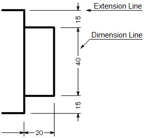
A technical drawing illustrating the use of extension lines and dimens (Source: 59d646f026634d9a)
- Section Lines (Hatching): Fine lines spaced evenly, usually 0.25 mm thick, to represent cut surfaces in sectional views.
2.1.3 Line Styles and Their Applications in Electronics Drawings
Understanding the appropriate use of line styles improves the readability and accuracy of electronic component drawings.
- Visible Edges and Boundaries: Drawn with continuous thick lines to outline components such as capacitors and IC packages.
- Hidden Features: Dashed lines show internal wiring or solder joints not visible from the outside.
- Center Lines and Axes: Chain lines mark the center of circular components like potentiometers and connectors.
- Cutting Planes: Thick chain lines with arrows indicate where a sectional view is taken, vital for illustrating internal PCB layers.
- Dimensioning: Thin continuous lines with arrowheads mark distances between component pins or board edges.
2.1.4 Conformance to Kenyan and International Standards
Kenyan electronics engineers must align with BS 8888 and ISO 128 to produce universally acceptable drawings.
- BS 8888: Specifies line types, thicknesses, and symbols for engineering drawings, including electronics.
- ISO 128: Provides guidelines for general principles of presentation in technical drawings.
- Kenya Bureau of Standards (KEBS): Adopts these international standards to ensure local compliance.
- Title Blocks and Drawing Borders: Standardized formats include line conventions to frame the drawing area.
- Drawing Scales: Use appropriate scale ratios (e.g., 1:1 for small components, 1:5 for larger assemblies) with line weights adjusted accordingly.
Practice Questions
- Identify and describe five types of lines used in electronics technical drawings, explaining their specific applications. (10 marks)
- Explain the importance of line thickness in technical drawings and state the recommended thickness ranges for visible and hidden lines. (8 marks)
- Using BS 8888 and ISO 128, outline the conventions for center lines and cutting planes in electronics drawings. (7 marks)
- Given a simple PCB layout, indicate which line types would be used to show visible outlines, hidden tracks, and center axes. (10 marks)
The rest of this chapter
🔒Create a free account to open more of this chapter.
Free: practical guides, quick cards, workplace scenarios and more.
Create a free account 🔒2.2 Freehand Printing of Letters
Legible lettering is critical in electronics technical drawings for clear communication of component labels, dimensions, and notes. Kenyan electronics engineers must master freehand printing to produce consistent and professional documentation without relying…
🔒2.3 Borderlines and title blocks
In electronics engineering technical drawings, borderlines and title blocks form the fundamental framework that ensures clarity, consistency, and professionalism. Kenyan electronics technicians and engineers rely on these conventions to communicate design inte…
🔒2.4 Construction of different angles
Accurate angle construction is critical in electronics engineering drawings, especially when designing component layouts, mounting brackets, or custom enclosures. Kenyan engineers and technicians frequently create angles to specify leads, connectors, or circui…
🔒2.5 Measurement of different angles
In Electronics Engineering, precise measurement of angles is essential during layout design, PCB drafting, and component placement. Accurate angle measurement ensures correct alignment of circuit elements and facilitates the interpretation of technical drawing…
🔒2.6 Bisection of different angles and lines
Accurate bisection of angles and lines is critical in electronics engineering for creating symmetrical layouts, dividing circuitry into equal parts, and placing components precisely. In Kenya’s electronics manufacturing and repair industries, technicians regul…
🔒2.7 Construction of geometric figures
In Electronics Engineering, precise geometric figure construction is essential for designing circuit layouts, electronic components, and system enclosures. Mastery of plane geometry drawing ensures accuracy in PCB design, component placement, and mechanical fi…
🔒2.8 Patterns development e.g cones, pyramids, prisms, cylinders
In electronics engineering, the ability to develop accurate patterns for three-dimensional shapes such as cones, pyramids, prisms, and cylinders is essential when designing enclosures, housings, and components that require precise fabrication. These patterns s…
🔒2.9 Different types of Tangents
Tangents are fundamental in electronics engineering drawings, especially when representing components like coils, circular connectors, and mechanical parts that interface with circular features. Understanding different types of tangents improves accuracy in di…
🔒2.10 Standard drawing conventions
In Electronics Engineering in Kenya, adherence to standard drawing conventions is crucial for creating clear, consistent, and universally understandable technical drawings. These conventions ensure that engineers, technicians, and fabricators can interpret dra…
Chapter Summary
This chapter covered essential aspects of producing plane geometry drawings, beginning with the identification and application of various types of lines used in technical drawings. It emphasized the importance of freehand printing of letters for clear and professional communication on drawings. The role of borderlines and title blocks was explained as a fundamental part of organizing and presenting drawing information. Detailed procedures for constructing and measuring different angles were presented, followed by methods for bisecting angles and lines accurately. The chapter then focused on the construction of key geometric figures including circles, triangles, rectangles, parallelograms, polygons, pyramids, conic sections, and prisms, ensuring students understand each shape’s properties and drawing techniques. It also introduced the development of patterns for three-dimensional shapes such as cones, pyramids, prisms, and cylinders. The study of tangents was divided into exterior and interior tangents to circles, highlighting their construction principles. Finally, the chapter concluded with standard drawing conventions that govern line types, scales, symbols, and title blocks, ensuring drawings meet recognized quality and clarity standards.
Self-Assessment
🔒 PDFDownload this self-assessment, with answers
A. Written Assessment
- What type of line is used to represent hidden edges in a technical drawing? (2 marks)
- Identify the correct sequence for freehand printing of capital letters in technical drawings. (3 marks)
🔒20 more in this section.
Chapter Examination Questions
🔒 PDFDownload these examination questions, with worked answers
SECTION A (40 Marks) - Answer ALL Questions
- Identify and describe four different types of lines used in electronic circuit drawings and their significance in Kenya Power and Lighting Company (KPLC) schematic diagrams. (4 marks)
- Explain the importance of freehand printing of letters in preparing electronic equipment labels used in hospital biomedical engineering workshops. (4 marks)
🔒18 more in this section.
Chapter Practical Activities
Practical 1: Drawing and Identifying Types of Lines in Plane Geometry
Electronics Engineering · Level 5
Technical Drawing
PRACTICAL ASSESSMENT
TIME: 4 HOURS
⬇ PDFCandidate Instructions (Candidate Tool)
Type: Individual
INSTRUCTIONS TO CANDIDATE:
1. You are required to perform the following task:
i. Draw and correctly label a plane geometry drawing sheet 420mm x 297mm showing six types of lines according to standard drawing conventions.
2. You have been provided with the following resources for the practical task:
| Tools & Equipment | Materials |
|---|
| Drawing board | Drawing sheet (A3 size, 420mm x 297mm) |
| T-square | |
| Set squares | |
| Drawing pencils (2H, HB, 2B) | |
| Eraser | |
| Sharpener | |
| Scale ruler | |
| Lettering guide | |
⬇ PDFResources Required (Cutting List)
| S/N | Item | Quantity |
|---|
| 1 | Drawing board | 1 Pc per Candidate |
| 2 | T-square | 1 Pc per Candidate |
| 3 | Set squares (45° and 30°-60°) | 1 set per Candidate |
| 4 | Drawing pencils (2H, HB, 2B) | 1 set per Candidate |
| 5 | Eraser | 1 Pc per Candidate |
| 6 | Sharpener | 1 Pc per Candidate |
| 7 | Scale ruler (metric, 300mm) | 1 Pc per Candidate |
| 8 | Drawing sheet (A3 size, 420mm x 297mm) | 1 Pc per Candidate |
| 9 | Lettering guide | 1 Pc per Candidate |
⬇ PDFAssessor Guide
| Items to be Evaluated | Marks Available | Marks Obtained | Comments |
|---|
| TASK 1: Preparation and Setup |
Wore Personal Protective Equipment (dustcoat/overall)
(Award 1 mark or 0) | 1 | | |
Ensured clean and organized working area before starting
(Award 1 mark or 0) | 1 | | |
Selected and arranged drawing tools and materials properly
(Award 1 mark or 0) | 1 | | |
| Sub-Total | 3 | | |
| TASK 2: Drawing Types of Lines |
Drew a continuous thick line (object line) 150mm long
(Award 3 marks or 0) | 3 | | |
Drew a continuous thin line (dimension line) 120mm long with arrowheads
(Award 3 marks or 0) | 3 | | |
Drew a dashed thin line (hidden line) 100mm long with correct dash spacing
(Award 3 marks or 0) | 3 | | |
Drew a chain thin line (centre line) 130mm long with alternating long and short dashes
(Award 3 marks or 0) | 3 | | |
Drew a zigzag thin line (break line) approximately 100mm long
(Award 3 marks or 0) | 3 | | |
Drew a phantom thin line (long dash, two short dashes) 120mm long
(Award 3 marks or 0) | 3 | | |
Used appropriate pencil grades for each line type
(Award 2 marks or 0) | 2 | | |
| Sub-Total | 20 | | |
| TASK 3: Labelling and Finishing |
Correctly labelled each type of line clearly and neatly using lettering guide
(Award 5 marks or 0) | 5 | | |
Used standard line type names and abbreviations in labels
(Award 3 marks or 0) | 3 | | |
Cleaned the drawing sheet of any smudges or unwanted marks
(Award 2 marks or 0) | 2 | | |
| Sub-Total | 10 | | |
| PRODUCT CHECKLIST |
Drawing sheet with six types of lines correctly drawn to specified lengths and standard conventions
(Award 12 marks or 0) | 12 | | |
Labels are accurate, legible, and positioned correctly without clutter
(Award 7 marks or 0) | 7 | | |
Overall neatness and presentation of the drawing sheet
(Award 8 marks or 0) | 8 | | |
| Sub-Total | 27 | | |
| GRAND TOTAL | 60 | | |
ASSESSMENT OUTCOME: ☐ Competent ☐ Not Yet Competent (competent if at least 50%)
Practical 2: Freehand Printing of Letters 50mm High in Technical Drawing
Electronics Engineering · Level 5
Technical Drawing
PRACTICAL ASSESSMENT
TIME: 4 HOURS
⬇ PDFCandidate Instructions (Candidate Tool)
Type: Individual
INSTRUCTIONS TO CANDIDATE:
1. You are required to perform the following task:
i. Produce freehand printed letters of height 50mm, style block capitals, on an A3 drawing sheet.
2. You have been provided with the following resources for the practical task:
| Tools & Equipment | Materials |
|---|
| Drawing board | Drawing sheet A3 size (420mm x 297mm) |
| T-square 600mm | Dust coat/overall |
| Set square 45° and 60° | |
| 2H pencil | |
| Eraser | |
| Scale ruler (metric) | |
⬇ PDFResources Required (Cutting List)
| S/N | Item | Quantity |
|---|
| 1 | Drawing board | 1 Pc per Candidate |
| 2 | T-square 600mm | 1 Pc per Candidate |
| 3 | Set square 45° and 60° | 1 Set per Candidate |
| 4 | 2H pencil | 2 Pcs per Candidate |
| 5 | Eraser | 1 Pc per Candidate |
| 6 | Scale ruler (metric) | 1 Pc per Candidate |
| 7 | Drawing sheet A3 size (420mm x 297mm) | 1 Sheet per Candidate |
| 8 | Dust coat/overall | 1 Pc per Candidate |
⬇ PDFAssessor Guide
| Items to be Evaluated | Marks Available | Marks Obtained | Comments |
|---|
| TASK 1: Preparation and Setup |
Wore Personal Protective Equipment (dust coat/overall)
(Award 1 mark for wearing PPE or 0) | 1 | | |
Ensured clean and tidy working area before starting
(Award 1 mark for good housekeeping or 0) | 1 | | |
Selected and arranged drawing tools and materials properly
(Award 1 mark for proper tool arrangement or 0) | 1 | | |
| Sub-Total | 3 | | |
| TASK 2: Execution of Freehand Printing |
Used scale ruler to mark letter height of 50mm accurately
(Award 3 marks for correct dimension marking or 0) | 3 | | |
Freehand printed block capital letters legibly and proportionately
(Award up to 5 marks for neatness, legibility, and style) | 5 | | |
Maintained consistent spacing and alignment of letters
(Award 3 marks for uniform spacing and alignment or 0) | 3 | | |
Used eraser to clean construction lines and smudges neatly
(Award 2 marks for cleanliness or 0) | 2 | | |
| Sub-Total | 13 | | |
| PRODUCT CHECKLIST |
Letters printed with height exactly 50mm ±2mm
(Award 4 marks for correct letter height or 0) | 4 | | |
Letters conform to block capital style as per drawing standards
(Award 5 marks for style conformity or 0) | 5 | | |
Letters are evenly spaced and aligned horizontally on the sheet
(Award 4 marks for spacing and alignment or 0) | 4 | | |
Drawing sheet is clean with no smudges or unnecessary marks
(Award 3 marks for neatness or 0) | 3 | | |
| Sub-Total | 16 | | |
| GRAND TOTAL | 32 | | |
ASSESSMENT OUTCOME: ☐ Competent ☐ Not Yet Competent (competent if at least 50%)
🔒Drawing Borderlines and Title Block on A3 Drawing SheetPractical 3
🔒Constructing and Measuring Various Angles Using Geometric ToolsPractical 4
🔒Bisecting angles and line segments using compass and straightedgePractical 5
🔒Construction of circles and related elementsPractical 6
🔒Drawing of Triangles Given Sides and AnglesPractical 7
🔒Drawing Rectangles and Parallelograms to Given Dimensions and AnglesPractical 8
🔒Construction of Regular Polygons Inscribed in CirclesPractical 9
🔒Draw plan and elevation views of pyramids with given base shapes and heightsPractical 10
🔒Draw plan and elevation views of a hexagonal prismPractical 11
🔒Draw Plane Geometry Conic Sections Using Standard MethodsPractical 12
🔒Develop true shape patterns for cones, pyramids, prisms, and cylindersPractical 13
🔒Drawing Exterior and Interior Tangents to CirclesPractical 14
🔒Plane Geometry Drawing with Combined Constructions and AnnotationsPractical 15
