Bell and alarm systems are essential components in various Kenyan workplaces, including hospitals, educational institutions, banks, and county government offices. Understanding how to interpret bell and alarm installation drawings is crucial for technicians and facility managers to ensure proper installation, maintenance, and troubleshooting. This chapter introduces the fundamental principles of bell and alarm circuits and guides students on reading and applying circuit diagrams in practical settings.
1.1 Bell and Alarm Circuits
1.1.1 Bell Circuit Diagrams
Bell circuit diagrams are graphical representations that detail the electrical connections and components within bell systems. These diagrams serve as blueprints during installation and maintenance.
Components of Bell Circuit Diagrams
-
Power Supply: Supplies electrical energy to the circuit, typically 12V or 24V DC in modern installations, ensuring consistent operation.
-
Bell or Buzzer: The output device that produces sound when energized; it converts electrical signals into audible alerts.
- Switch: Controls the flow of current; activating the switch completes the circuit and triggers the bell.
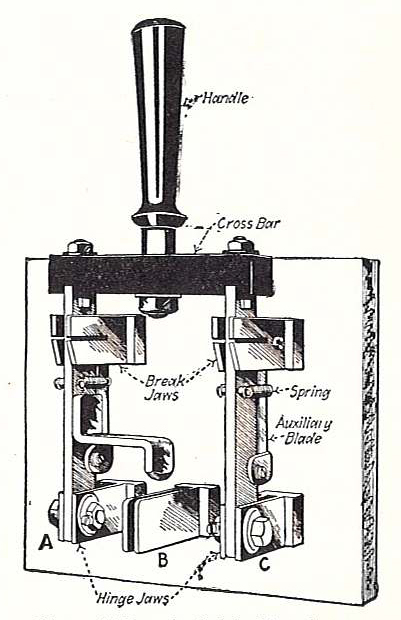
Diagram of a manual electrical switch (Source: Wikimedia Commons)
-
Resistors: Manage current within the circuit to protect components from damage due to excessive current.
-
Wiring Connections: Represented by lines, these show how components are electrically connected, indicating series or parallel arrangements.
Reading Bell Circuit Symbols and Lines
- Lines: Solid lines indicate conducting wires; dashed lines may represent control wiring or mechanical linkage.
- Switch Symbol: Depicted as a break in the line with a pivot; open switch shows no current flow, closed switch completes the circuit.
- Bell Symbol: Usually a circle with a “bell” shape or buzzer indicator, showing the sound-producing element.
- Connection Dots: Where lines intersect with a dot, it signifies an electrical junction; lines crossing without dots mean no connection.
- Polarity Marks: Indicate positive and negative terminals to ensure correct power supply connection.
Types of Bell Circuit Configurations
- Series Circuit: Components connected end-to-end; current flows through each component sequentially. A break anywhere stops the entire circuit.
- Parallel Circuit: Components connected across the same voltage source; each operates independently. If one component fails, others continue functioning.
- Combination Circuit: Integrates series and parallel elements to achieve specific operational functions.
- Latching Circuit: Uses relays or switches to maintain the bell in an energized state until manually reset.
Step-by-Step Procedure to Interpret a Bell Circuit Diagram
- Identify the Power Source: Locate the voltage rating and polarity to understand circuit requirements.
- Trace the Wiring Paths: Follow the lines from the power source through switches and components to the bell.
- Recognize Symbols: Match symbols to components such as switches, resistors, and the bell.
- Determine Circuit Type: Assess if the circuit is series, parallel, or combination.
- Check for Control Elements: Identify any relays or additional switches controlling the circuit.
- Verify Connections: Look for junctions and ensure continuity where lines connect.
Practice Questions
- Identify and explain the symbols used in a basic bell circuit diagram. (5 marks)
- Describe the differences between series and parallel bell circuits using diagram interpretation. (6 marks)
- Given a bell circuit diagram with a switch and resistor, trace the current flow when the switch is closed. (5 marks)
1.1.2 Definition, Purpose and Applications of Bell and Alarm Circuits
Bell and alarm circuits are designed to provide audible or visual alerts in various environments. Their correct design and interpretation are vital to ensure safety and communication effectiveness.
Definition of Bell and Alarm Circuits
- Bell Circuit: An electrical circuit that activates a bell or buzzer to produce sound, signaling an event or status.
- Alarm Circuit: Similar to bell circuits but often integrated with sensors and control devices to detect abnormal conditions.
- Control Elements: Include switches, relays, and timers that regulate when alarms or bells are activated.
- Power Source: Provides electrical energy, often from batteries or mains power with suitable transformers.
- Output Devices: Bells, buzzers, or sirens that generate audible alerts or indicators.
Purpose of Bell and Alarm Circuits
- Communication: Facilitate notification across distances, such as calling staff in a hospital ward.
- Warning: Alert occupants to emergencies like fire or intrusion in county government offices.
- Process Control: Signal status changes in industrial or agricultural processes.
- Access Control: Indicate door openings or request for entry in banks and retail businesses.
- Safety Enhancement: Provide timely alerts that reduce risk of accidents or damage.
Applications of Bell and Alarm Circuits in Kenyan Sectors
- Hospitals: Nurse call systems to summon assistance quickly.
- Schools and Universities: Class change bells to regulate schedules.
- Banks and SACCOs: Security alarms to deter unauthorized access.
- County Government Offices: Fire alarms integrated with emergency response.
- Hotels and Retail Businesses: Doorbell systems for customer service.
Benefits of Proper Bell and Alarm Circuit Installation
- Reliability: Ensures alerts function without failure, critical in safety applications.
- Efficiency: Enables fast response to events, improving operational workflow.
- Cost-Effectiveness: Minimizes downtime and repair costs through clear circuit design.
- User-Friendly: Simplifies operation and maintenance for facility staff.
- Compliance: Meets safety and regulatory standards such as those from NEMA.
Practice Questions
- Define a bell circuit and an alarm circuit, highlighting key differences. (6 marks)
- List five purposes of alarm circuits in county government offices. (5 marks)
- Explain why proper installation of bell and alarm circuits is critical in hospitals. (6 marks)
The rest of this chapter
🔒Create a free account to open more of this chapter.
Free: practical guides, quick cards, workplace scenarios and more.
Create a free account 🔒1.2 Definition, Purpose and Applications of Bell and Alarm Circuits
Understanding the fundamental definitions, purposes, and sector-specific applications of bell and alarm circuits is essential for technicians working across diverse Kenyan industries. This knowledge supports the design, installation, and maintenance of effecti…
🔒1.3 Bell and Alarm Symbols
Bell and alarm installation drawings rely heavily on standardized symbols to represent various components and devices. Understanding these symbols is essential for technicians and installers working across sectors such as county hospitals, universities, banks,…
🔒1.4 Mapping Wiring System
Mapping the wiring system in bell and alarm installation drawings is fundamental for ensuring that electrical circuits are correctly planned, connected, and maintained. This process is vital across Kenyan sectors such as county government offices, farms, unive…
🔒1.5 Types of Bell Circuits
Bell circuits are fundamental in alert and notification systems across various Kenyan workplaces such as hospitals, schools, banks, and government offices. Understanding the different types of bell circuits enables technicians to select and install the appropr…
🔒1.6 Interpreting Bell Circuit Diagrams
Interpreting bell circuit diagrams is an essential skill for installation and maintenance in various sectors such as schools, banks, and retail businesses. These diagrams provide a visual representation of the electrical connections and components, enabling te…
Chapter Summary
This chapter focused on bell and alarm installation drawings, beginning with an exploration of bell circuit diagrams that illustrate the connections and components involved. It clarified the definition, purpose, and various applications of bell and alarm circuits, emphasizing their role in alert and notification systems. The chapter then introduced common bell and alarm symbols used in technical drawings, enabling clear and standardized interpretation. Mapping wiring systems were discussed to show how wiring layouts correspond to physical installations. Various types of bell circuits were presented, highlighting differences in design and functionality. Finally, the chapter provided detailed guidance on interpreting bell circuit diagrams, equipping students with the skills to read and understand these essential technical documents accurately.
Self-Assessment
🔒 PDFDownload this self-assessment, with answers
A. Written Assessment
- What is the primary purpose of a bell circuit in a county referral hospital setting? (2 marks)
- Identify the symbol used to represent a bell in a standard bell circuit diagram according to BS standards. (2 marks)
🔒20 more in this section.
Chapter Examination Questions
🔒 PDFDownload these examination questions, with worked answers
SECTION A (40 Marks) - Answer ALL Questions
- Identify the main components of a simple bell circuit diagram used in a county referral hospital (4 marks)
- Explain the purpose of an alarm circuit in a retail business premises (4 marks)
🔒18 more in this section.
Chapter Practical Activities
Practical 1: Identify and Explain Bell and Alarm Circuit Components
Electrical Engineering · Level 5
Bell And Alarm Installation
PRACTICAL ASSESSMENT
TIME: 4 HOURS
⬇ PDFCandidate Instructions (Candidate Tool)
Type: Individual
INSTRUCTIONS TO CANDIDATE:
1. You are required to perform the following task:
i. Identify and explain all bell and alarm circuit components installed on a 600mm x 450mm installation board.
2. You have been provided with the following resources for the practical task:
| Tools & Equipment | Materials |
|---|
| Multimeter | 1.5 mm2 PVC sheathed cable |
| Spirit level | 2.5 mm2 PVC sheathed cable |
| Screwdriver | Bell unit (12 V DC) |
| Pliers | Alarm siren (12 V DC) |
| Wire stripper | 12 V DC power supply |
| Cable clips | Single pole switch |
| Junction box |
| Wood screws |
| PPE (Gloves, Goggles, Dustcoat) |
⬇ PDFResources Required (Cutting List)
| S/N | Item | Quantity |
|---|
| 1 | 1.5 mm2 PVC sheathed cable | 5 Metres per Candidate |
| 2 | 2.5 mm2 PVC sheathed cable | 3 Metres per Candidate |
| 3 | Bell unit (12 V DC) | 1 Pc per Candidate |
| 4 | Alarm siren (12 V DC) | 1 Pc per Candidate |
| 5 | 12 V DC power supply | 1 Pc per Candidate |
| 6 | Single pole switch | 1 Pc per Candidate |
| 7 | Junction box | 1 Pc per Candidate |
| 8 | Cable clips | 1 pkt per Candidate |
| 9 | Wood screws | 10 Pcs per Candidate |
| 10 | Multimeter | 1 Pc per Candidate |
| 11 | Spirit level | 1 Pc per Candidate |
| 12 | PPE (Gloves, Goggles, Dustcoat) | 1 Set per Candidate |
⬇ PDFAssessor Guide
| Items to be Evaluated | Marks Available | Marks Obtained | Comments |
|---|
| TASK 1: Component Identification and Explanation |
Wore personal protective equipment (PPE)
(Award 1 or 0) | 1 | | |
Applied good housekeeping practice ensuring a clean working area
(Award 1 or 0) | 1 | | |
Correctly identified all bell and alarm circuit components on the installation board
(Award 1 mark per correct component identified, total 5 marks) | 5 | | |
Accurately explained the function of each identified component
(Award 1 mark per correct explanation, total 6 marks) | 6 | | |
Demonstrated correct use of multimeter to test circuit continuity
(Award 3 or 0) | 3 | | |
Ensured safe and neat wiring connections with correct cable sizes
(Award 4 or 0) | 4 | | |
Completed task within allocated time
(Award 2 or 0) | 2 | | |
| Sub-Total | 22 | | |
| PRODUCT CHECKLIST |
Installation board dimensions 600mm x 450mm within ±2mm tolerance
(Award 2 or 0) | 2 | | |
All components firmly fixed and level on board
(Award 3 or 0) | 3 | | |
Circuit wiring is neat, cables clipped at 300mm intervals horizontally and vertically
(Award 4 or 0) | 4 | | |
Correct cable termination with no nicks and proper twisting/folding
(Award 3 or 0) | 3 | | |
Circuit operates correctly when powered (bell and alarm sound on switch activation)
(Award 6 or 0) | 6 | | |
| Sub-Total | 18 | | |
| GRAND TOTAL | 40 | | |
ASSESSMENT OUTCOME: ☐ Competent ☐ Not Yet Competent (competent if at least 50%)
Practical 2: Interpret and Analyze Bell and Alarm Circuit Diagrams
Electrical Engineering · Level 5
Bell And Alarm Installation
PRACTICAL ASSESSMENT
TIME: 4 HOURS
⬇ PDFCandidate Instructions (Candidate Tool)
Type: Individual
INSTRUCTIONS TO CANDIDATE:
1. You are required to perform the following task:
i. Interpret and produce a detailed bell and alarm circuit diagram with components spaced on a 1000mm x 1000mm board as per the provided schematic.
2. You have been provided with the following resources for the practical task:
| Tools & Equipment | Materials |
|---|
| Multimeter | 1.5 mm2 PVC sheathed cable |
| Pliers | 2.5 mm2 single core cable |
| Screwdriver | Bell unit (12V DC) |
| Wire stripper | Alarm siren (12V DC) |
| Cable clips | 12V DC power supply |
| Spirit level | Push button switch (1 gang one way) |
| Junction box |
| Installation board (wooden, 1m x 1m) |
| Cable clips (12mm) |
| Insulation tape |
⬇ PDFResources Required (Cutting List)
| S/N | Item | Quantity |
|---|
| 1 | 1.5 mm2 PVC sheathed cable | 5 Metres per Candidate |
| 2 | 2.5 mm2 single core cable | 3 Metres per Candidate |
| 3 | Bell unit (12V DC) | 1 Pc per Candidate |
| 4 | Alarm siren (12V DC) | 1 Pc per Candidate |
| 5 | 12V DC power supply | 1 Pc per Candidate |
| 6 | Push button switch (1 gang one way) | 1 Pc per Candidate |
| 7 | Junction box | 1 Pc per Candidate |
| 8 | Multimeter | 1 Pc per Candidate |
| 9 | PPE (Gloves, dustcoat, safety boots) | 1 set per Candidate |
| 10 | Installation board (wooden, 1m x 1m) | 1 Pc per Candidate |
| 11 | Cable clips (12mm) | 1 pkt per Candidate |
| 12 | Insulation tape | 1 roll per Candidate |
⬇ PDFAssessor Guide
| Items to be Evaluated | Marks Available | Marks Obtained | Comments |
|---|
| TASK 1: Interpretation and Layout of Bell and Alarm Circuit |
Wore personal protective equipment (gloves, dustcoat, safety boots)
(Award 1 or 0) | 1 | | |
Applied good housekeeping: ensured clean working area before starting
(Award 1 or 0) | 1 | | |
Identified and listed all components in the bell and alarm circuit diagram
(Award 1 mark for each correct component x 2) | 2 | | |
Interpreted circuit connections correctly between bell, alarm, switch, power supply, and junction box
(Award 3 or 0) | 3 | | |
Drew the detailed bell and alarm circuit diagram on the 1000mm x 1000mm board
(Award 5 or 0) | 5 | | |
Used correct symbols and annotations for all components
(Award 2 or 0) | 2 | | |
Applied correct colour coding and wire sizes in the interpretation
(Award 2 or 0) | 2 | | |
| Sub-Total | 16 | | |
| TASK 2: Circuit Testing and Verification |
Performed continuity test on circuit wiring
(Award 3 or 0) | 3 | | |
Verified correct circuit operation: bell sounds when push button is pressed
(Award 5 or 0) | 5 | | |
Verified correct circuit operation: alarm siren activates on alarm trigger
(Award 5 or 0) | 5 | | |
Demonstrated safe handling of tools and equipment during testing
(Award 2 or 0) | 2 | | |
| Sub-Total | 15 | | |
| PRODUCT CHECKLIST |
Finished circuit diagram accuracy: component placement within 10mm tolerance on 1000mm x 1000mm board
(Award 3 or 0) | 3 | | |
Finished circuit diagram correctness: all connections correctly represented as per schematic
(Award 4 or 0) | 4 | | |
Finished circuit diagram neatness and clarity: lines straight, symbols clear and legible
(Award 3 or 0) | 3 | | |
| Sub-Total | 10 | | |
| GRAND TOTAL | 41 | | |
ASSESSMENT OUTCOME: ☐ Competent ☐ Not Yet Competent (competent if at least 50%)
🔒Draw Bell and Alarm Circuit Diagrams 600mm x 400mmPractical 3
🔒Identify and Use Standard Bell and Alarm Symbols in Circuit DrawingPractical 4
🔒Map wiring system for bell and alarm circuits as per provided layoutPractical 5
🔒Assemble simple bell circuits with control wiringPractical 6
🔒Test and Troubleshoot Bell Circuits for Proper FunctionalityPractical 7
🔒Plan and Layout Bell and Alarm Circuit Installation on SitePractical 8
🔒Identify and Explain Different Types of Bell CircuitsPractical 9
🔒Interpret combined bell and alarm installation drawings and prepare wiring layoutPractical 10
