
Compiled by: Simon Githaiga
Waste water infrastructure design reports are essential documents in civil engineering projects, especially in Kenya where urbanisation and industrial growth demand efficient sanitation systems. These reports detail the design elements, construction appurtenances, and operational considerations necessary for sustainable waste water management. Understanding the components like valves, fire hydrants, meters, chambers, meter chambers, and surge tanks is critical to preparing comprehensive reports that guide construction and maintenance phases effectively.
Construction appurtenances are auxiliary components integrated into waste water infrastructure to ensure operational control, safety, and monitoring of the system. In Kenya’s civil engineering practice, appurtenances are vital for managing flow, preventing contamination, and facilitating maintenance in municipal and industrial waste water networks. This section explores key appurtenances commonly specified in design reports to support system functionality and durability.
Valves control the flow and pressure within waste water pipelines, providing essential regulation and isolation capabilities. Their correct specification and placement in the system prevent backflow, enable repairs without system shutdown, and protect infrastructure from pressure surges.
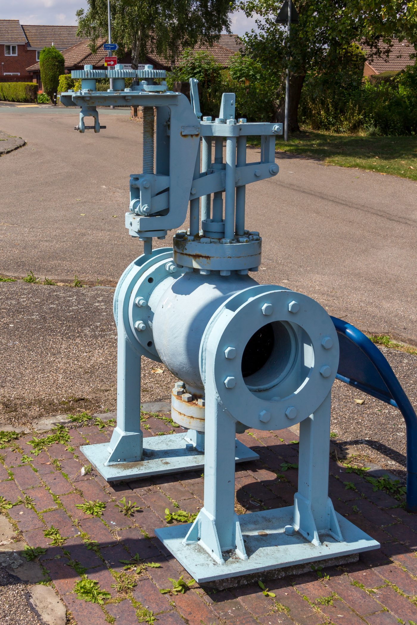
Large industrial gate valve outdoors (Source: Wikimedia Commons)
A gate valve closes off flow by lowering a flat or wedge-shaped gate across the full bore of the pipe, operated by a handwheel or key turning a threaded stem. When fully open, the gate is withdrawn completely from the flow path, so solids in waste water pass freely and head loss is very low, which makes gate valves the usual choice for isolating sewage rising mains, pump stations and treatment units. For sewage, resilient-seated or knife gate valves are preferred, because a knife-edged gate cuts through rags and solids that would stop a wedge from sealing. Example: the pump station serving a county hospital’s sewage rising main had knife gate valves on each pump outlet so that one pump could be removed for repair while the other kept running.
A globe valve regulates flow by moving a disc or plug towards or away from a seat inside a rounded body, with the liquid changing direction as it passes through. It gives fine and accurate flow control and a tight seal, but its narrow, winding passage causes high head loss and traps solids, so it is not used on raw sewage lines. In waste water works, globe valves are used on clean or treated liquid lines such as chemical dosing, sampling, seal water and compressed air lines, and on treated effluent lines where flow must be set accurately. Example: at the treatment plant of a boarding school, small globe valves were fitted on the chlorine dosing line so that the operator could set the disinfectant dose precisely.
| Feature | Gate valve | Globe valve |
|---|---|---|
| Main use | Isolation | Regulation and throttling |
| Head loss when open | Very low | High |
| Handling of solids | Good (knife gate) | Poor, traps solids |
| Typical location | Rising mains, pump stations | Dosing, sampling and clean water lines |
| Flow control | Poor | Fine and accurate |
A check valve (non-return valve) lets waste water flow in one direction only and closes automatically when flow tries to reverse. On a sewage pumping main, it stops the column of sewage in the rising main from draining back through the pump when the pump stops, which would otherwise spin the pump backwards and flood the wet well. It is also used at outfalls and on connections where backflow could cause flooding or contamination. Example: at a hotel’s sewage pump station, a ball check valve on each pump discharge prevented sewage from returning to the sump every time the pumps switched off.
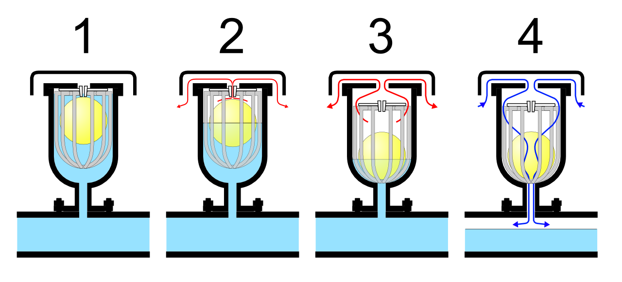
Operation of air release valve stages (Source: Wikimedia Commons)
Air relief valves remove air and gases from pressurised waste water pipelines and, in some types, let air in to prevent vacuum. Sewage rising mains collect air and also sewage gases such as hydrogen sulphide at high points, which reduce flow capacity, cause surges and corrode the pipe crown. Valves made for sewage have a longer body and special float mechanism so that solids and grease do not reach and block the air outlet, and they are installed at high points and changes of gradient with an isolating valve below for maintenance. Example: the rising main from an abattoir in Athi River lost capacity until sewage air valves were fitted at its two high points, after which the pumps again delivered their design flow.
| Type | Function | Typical location |
|---|---|---|
| Air release valve | Releases small amounts of air while the main is under pressure | High points of rising mains |
| Air and vacuum valve | Releases large volumes of air on filling and admits air on draining | Pump discharges, high points |
| Combination (double) air valve | Combines both functions | Most high points on rising mains |
| Sewage air valve | Long-bodied valve that keeps solids away from the outlet | Raw sewage rising mains |
A pressure reducing valve (PRV) automatically lowers a high, varying upstream pressure to a lower, steady downstream pressure. In waste water systems, PRVs are used mainly on pressurised clean or treated lines, such as treated effluent reuse lines, wash water and service water lines, and on sewage pressure mains where a long downhill section would otherwise create excessive pressure at the low end. A PRV senses the downstream pressure and opens or closes its main valve to keep that pressure at the set value, and it is installed with isolating valves, a strainer, pressure gauges and a bypass. Example: a flower farm in Naivasha reusing treated effluent for irrigation fitted a PRV where its pipeline dropped steeply into the valley, protecting the drip lines from bursting.
A treated effluent pipeline falls 90 m from a storage tank to an irrigation block. Find the static pressure at the bottom, and state the effect of a PRV set at 3 bar.
p = ρ × g × h
p = 1,000 × 9.81 × 90
p = 882,900 Pa = 8.8 bar
A PRV set at 3 bar reduces the pressure supplied to the irrigation block from about 8.8 bar to 3 bar.
Fire hydrants in waste water infrastructure serve dual roles: providing access to water for firefighting and facilitating system flushing and maintenance. Their integration into sewer systems or alongside pipelines supports emergency response and operational hygiene.
| Name | Specification | Use |
|---|---|---|
| Fire Hydrant | Pressure rating 10 bar | Firefighting and flushing |
| Outlet Diameter | 100 mm (4 inches) | Connection for fire hoses |
| Material | Cast iron with anti-corrosion coating | Durability and resistance to weather |
A wet barrel hydrant has its barrel (upright body) permanently full of water under mains pressure, with an individual valve behind each outlet. Because water is already in the barrel, each outlet can be opened independently and gives water immediately, which allows fire crews, or sewer maintenance crews using water for flushing, to connect quickly. Wet barrel hydrants suit Kenya’s generally frost-free climate, but they need protection from vehicle impact because damage to the barrel releases water. Example: a business park in Kisumu used wet barrel hydrants along its roads, and the same hydrants supplied water to jetting units that cleared its sewer lines.
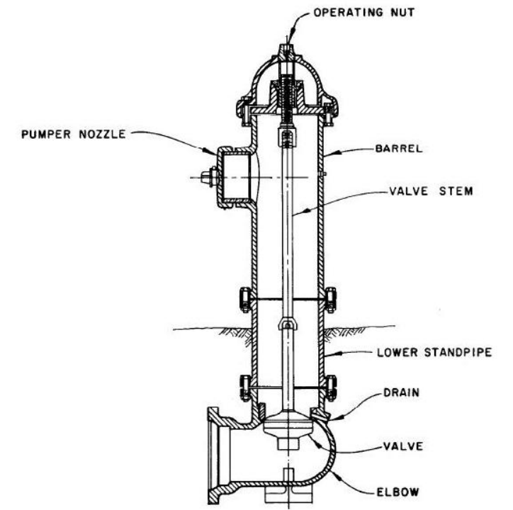
Dry barrel hydrant sectional diagram (Source: Wikimedia Commons)
A dry barrel hydrant has its main valve below ground at the base, so the barrel above ground is empty when the hydrant is closed and drains through a drain hole after use. Turning the operating nut on top opens the main valve, filling the barrel and supplying all outlets together. This design prevents freezing and limits water loss and contamination risk if the hydrant is damaged, which is useful at high altitude and in places exposed to vehicles or vandalism. Example: a county water department supplying a town on the slopes of Mount Kenya fitted dry barrel hydrants at exposed roadside sites.
Meters in waste water infrastructure measure flow rates and volumes, providing critical data for system monitoring, billing, and leak detection. Accurate metering supports operational efficiency and resource management in municipal and industrial settings.
Domestic meters are small water meters, usually 15 mm to 25 mm, fitted on household and small business water connections. Waste water from homes is rarely metered directly, so utilities use the water consumed, read from the domestic meter, to calculate sewerage charges, commonly assuming that a fixed proportion, often around 75% to 80%, returns to the sewer. Domestic meter records also help engineers estimate per capita water use and therefore the design flows for sewers. Example: a water and sewerage company billing an estate in Nakuru calculated each household’s sewer charge as a percentage of its metered water bill.
A household’s meter reading rose from 1,245 m³ to 1,263 m³ in a month. The utility charges sewerage at 75% of the water consumed at Ksh 60 per m³. Find the sewerage charge.
Water used = 1,263 − 1,245 = 18 m³
Sewage volume = 0.75 × 18 = 13.5 m³
Sewerage charge = 13.5 × 60
Sewerage charge = Ksh 810
Bulk meters are large meters, generally 50 mm and above, that measure large flows at strategic points in water and waste water systems. In waste water infrastructure they are installed on treatment works inlets and outlets, pumping station rising mains and the discharge points of large industrial customers, so that operators know how much waste water is received, treated and discharged. Because sewage contains solids, bulk meters for waste water are usually electromagnetic or ultrasonic, or open-channel devices such as flumes, rather than mechanical meters. Example: a brewery discharging effluent into a municipal sewer had a bulk electromagnetic meter on its outlet so that the county could bill its discharge by volume.
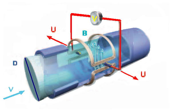
Electromagnetic flow meter diagram (Source: Wikimedia Commons)
An electromagnetic flow meter works on Faraday’s law of electromagnetic induction: as waste water, which conducts electricity, flows through a magnetic field set up by coils around the pipe, it generates a small voltage proportional to its velocity, which electrodes in the pipe wall measure and convert to a flow rate. The meter has a full, unobstructed bore and no moving parts, so solids, rags and grit pass through without blocking or wearing it, and it causes no extra head loss. It needs a power supply and must run with the pipe completely full to read correctly. Example: the inlet of a university’s sewage treatment plant was fitted with an electromagnetic meter, giving continuous flow records that showed when infiltration increased during the rains.
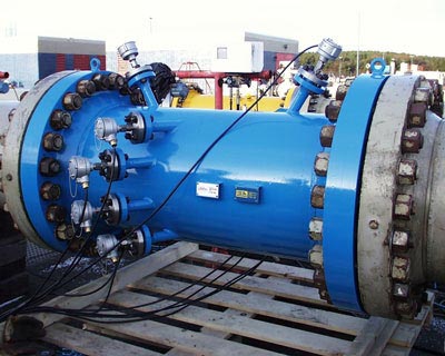
Industrial ultrasonic flow meter installed on pipeline (Source: Wikimedia Commons)
Chambers are structural enclosures that provide access to underground pipelines and appurtenances for inspection, maintenance, and flow regulation. Their design must consider safety, accessibility, and hydraulic efficiency.
A meter chamber is an enclosure built to house a flow meter and its fittings, protecting it from damage, flooding and tampering while allowing it to be read, calibrated and replaced. In waste water systems, meter chambers are built on rising mains, treatment works inlets and outlets, and industrial effluent discharge points, and they must hold the meter, isolating valves, a dismantling joint for removal and, for electromagnetic meters, the converter and cable entries. Because the chamber may contain sewage gases, it must be ventilated and treated as a confined space for entry. Example: a slaughterhouse connected to a municipal sewer built a meter chamber at its boundary, so that county staff could read and check the effluent meter without entering the factory.
A valve chamber is an underground enclosure that houses valves such as gate valves, check valves, air valves or washouts, so they can be operated, inspected and maintained. On sewage rising mains and in pump stations, valve chambers must be large enough to operate and remove the valves, have a sump or drain for spillage, and be ventilated because sewage gases are toxic and flammable. The pipe should pass through the chamber walls on flexible seals so that settlement of the chamber does not crack the pipe. Example: each air valve on the rising main from a cooperative coffee factory’s effluent pump station was housed in a ventilated concrete valve chamber with a lockable cover.
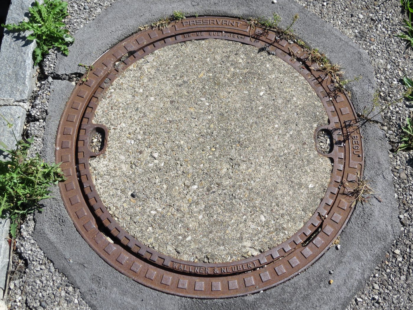
A manhole cover on a concrete surface (Source: Wikimedia Commons)
Meter chambers are specialized enclosures designed to house flow meters and associated instrumentation, protecting them from environmental damage and facilitating accurate flow measurement.
Surge tanks are protective appurtenances used to mitigate pressure fluctuations in waste water systems, preventing pipeline damage caused by water hammer and sudden changes in flow velocity.
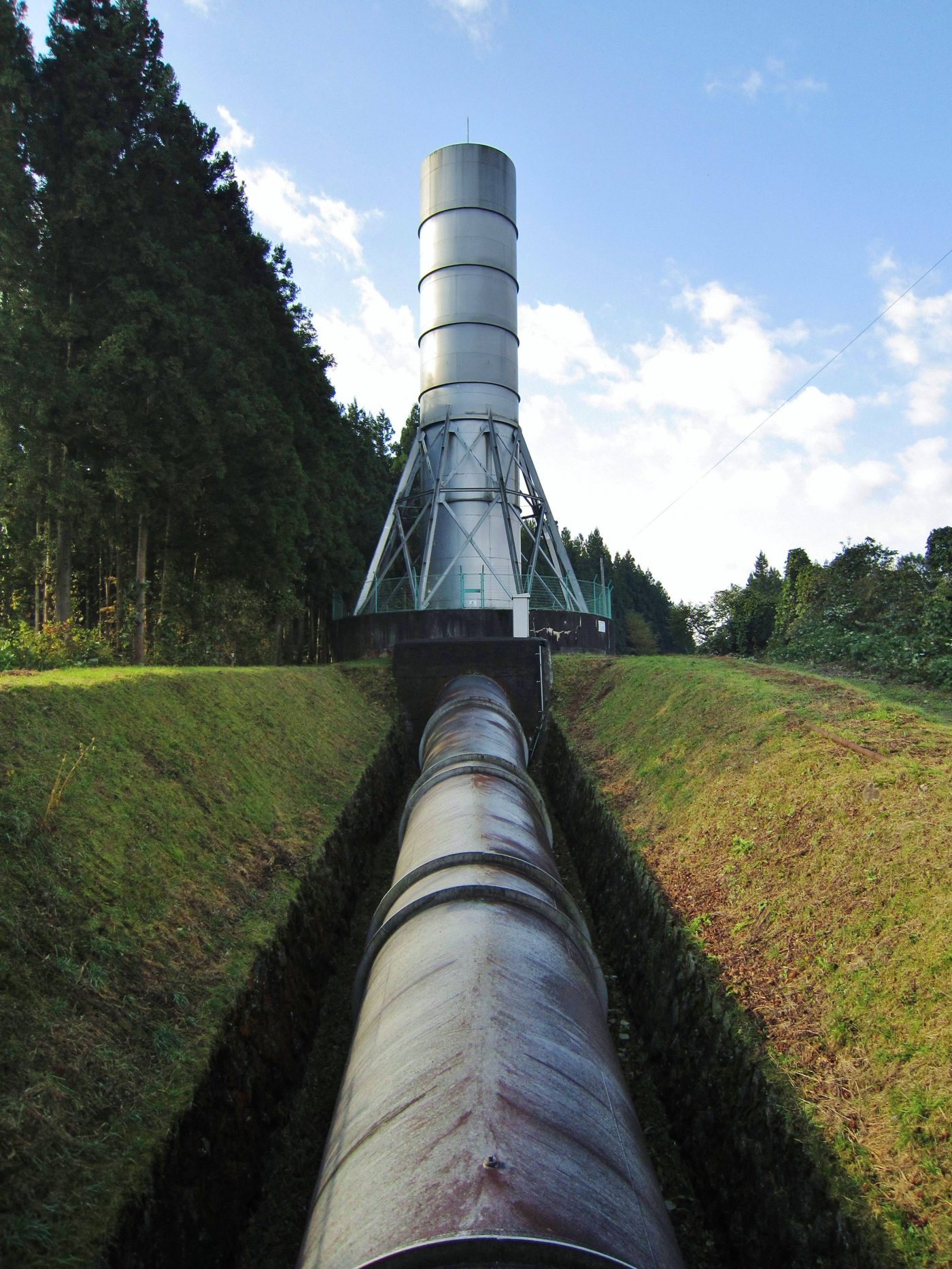
Open surge tank with pipeline in a trench (Source: Wikimedia Commons)
standpipe surge tank with pipeline (Source: Wikipedia (Surge tank))
| Name | Specification | Use |
|---|---|---|
| Volume | Calculated based on surge volume | To accommodate transient water volume |
| Height | Determined by pressure head requirements | To maintain system pressure balance |
| Material | Reinforced concrete or steel | Structural strength and durability |
Sewage flows at 2.0 m/s in a rising main when the pump suddenly stops. Taking the pressure wave speed as 1,100 m/s, estimate the pressure change.
Δp = ρ × c × Δv
Δp = 1,000 × 1,100 × 2.0
Δp = 2,200,000 Pa = 22 bar
A surge of this size could burst the main or collapse it under vacuum, which is why surge tanks or surge vessels are provided on long rising mains.
Describe the main types of valves used in waste water infrastructure and explain their specific functions. (10 marks)
Explain the design considerations for fire hydrants in urban waste water systems and their role beyond firefighting. (10 marks)
Compare electromagnetic and ultrasonic flow meters in terms of suitability for waste water flow measurement. (10 marks)
What are the critical safety features that must be incorporated into the design of waste water chambers? (10 marks)
Discuss the importance of surge tanks in protecting waste water pipelines and outline the factors influencing their design. (10 marks)
Create a free account to open more of this chapter.
Free: practical guides, quick cards, workplace scenarios and more.
Create a free accountThis chapter provides a comprehensive overview of preparing a wastewater infrastructure design report, beginning with an examination of construction appurtenances such as various types of valves including gate, globe, check, air relief, and pressure reducing valves, as well as fire hydrants categorized into wet barrel and dry barrel types. It also covers meters, distinguishing between domestic, bulk, and electromagnetic varieties, along with chambers for meters and valves, and the role of surge tanks in the system. The chapter then addresses the preparation of technical specifications that define the standards and requirements for the infrastructure components. Following this, the bill of quantities is explained, highlighting the importance of accurate measurements and cost estimations to ensure practical budgeting and resource allocation. The final section focuses on the technical design report itself, detailing the design methodology, specific design details, system components, and a thorough cost analysis that includes item descriptions, quantities, and recommended trainee ratios. Together, these elements form the essential framework for documenting and executing effective wastewater infrastructure projects.
Type: Individual
| Tools & Equipment | Materials |
|---|---|
| Wrench Spanner Set | Gate Valve DN100 |
| Pipe Wrench | Globe Valve DN80 |
| Pipe Cutter | Flanged Pipes DN100 |
| Measuring Tape 5m | Flanged Pipes DN80 |
| Marker Pen | Gasket for DN100 Flange |
| Gasket for DN80 Flange | |
| Bolts and Nuts M16 |
| S/N | Item | Quantity |
|---|---|---|
| 1 | Gate Valve DN100 | 1 Pc per Candidate |
| 2 | Globe Valve DN80 | 1 Pc per Candidate |
| 3 | Flanged Pipes DN100 | 2 Pcs per Candidate |
| 4 | Flanged Pipes DN80 | 2 Pcs per Candidate |
| 5 | Gasket for DN100 Flange | 2 Pcs per Candidate |
| 6 | Gasket for DN80 Flange | 2 Pcs per Candidate |
| 7 | Bolts and Nuts M16 | 16 Pcs per Candidate |
| 8 | Wrench Spanner Set | 1 Set per 3 Candidates |
| 9 | Pipe Wrench | 1 Pc per Candidate |
| 10 | Pipe Cutter | 1 Pc per Candidate |
| 11 | Measuring Tape 5m | 1 Pc per Candidate |
| 12 | Marker Pen | 1 Pc per Candidate |
| 13 | Safety Helmet | 1 Pc per Candidate |
| 14 | Safety Boots | 1 Pair per Candidate |
| 15 | Protective Gloves | 1 Pair per Candidate |
| 16 | Overall | 1 Pc per Candidate |
| Items to be Evaluated | Marks Available | Marks Obtained | Comments |
|---|---|---|---|
| TASK 1: Safety and Preparation | |||
| Wore PPE (Safety Helmet, Safety Boots, Gloves, Overall) (Award 3 marks or zero) | 3 | ||
| Used tools and equipment correctly as per job requirements (Award 2 marks or zero) | 2 | ||
| Sub-Total | 5 | ||
| TASK 2: Setting Out and Measurement | |||
| Measured and marked pipe sections accurately within ±2mm tolerance (Award 3 marks or zero) | 3 | ||
| Cut pipes to correct lengths as per drawing (Award 3 marks or zero) | 3 | ||
| Prepared pipe ends cleanly for valve installation (Award 2 marks or zero) | 2 | ||
| Sub-Total | 8 | ||
| TASK 3: Valve Installation | |||
| Installed gate valve DN100 correctly with proper flange alignment (Award 6 marks or zero) | 6 | ||
| Installed globe valve DN80 correctly with proper flange alignment (Award 6 marks or zero) | 6 | ||
| Fitted gaskets properly to prevent leakage (Award 3 marks or zero) | 3 | ||
| Tightened bolts and nuts evenly and to correct torque (Award 4 marks or zero) | 4 | ||
| Sub-Total | 19 | ||
| TASK 4: Testing and Final Checks | |||
| Checked valve operation (open/close functions smoothly) (Award 3 marks or zero) | 3 | ||
| Checked for leaks after installation (Award 3 marks or zero) | 3 | ||
| Cleaned work area and disposed of waste properly (Award 2 marks or zero) | 2 | ||
| Sub-Total | 8 | ||
| PRODUCT CHECKLIST | |||
| Gate valve DN100 installed as per drawing dimensions and orientation (Award 6 marks or zero) | 6 | ||
| Globe valve DN80 installed as per drawing dimensions and orientation (Award 6 marks or zero) | 6 | ||
| Flange bolt holes aligned and bolt tightness uniform (Award 4 marks or zero) | 4 | ||
| No visible leaks or damages on valves and pipe connections (Award 4 marks or zero) | 4 | ||
| Sub-Total | 20 | ||
| GRAND TOTAL | 60 | ||
Type: Individual
| Tools & Equipment | Materials |
|---|---|
| Hand saw for PVC | Check valve 100mm diameter |
| Pipe wrench | Air relief valve 100mm diameter |
| Adjustable spanner | PVC pipe 100mm diameter |
| Measuring tape 5m | PVC pipe fittings 100mm diameter |
| Marker pen | PVC solvent cement |
| Teflon tape |
| S/N | Item | Quantity |
|---|---|---|
| 1 | Check valve 100mm diameter | 1 Pc per Candidate |
| 2 | Air relief valve 100mm diameter | 1 Pc per Candidate |
| 3 | PVC pipe 100mm diameter, length 1000mm | 1 Pc per Candidate |
| 4 | PVC pipe fittings (couplings, elbows) 100mm diameter | 3 Pcs per Candidate |
| 5 | PVC solvent cement | 1 Can per 3 Candidates |
| 6 | Teflon tape roll | 1 Roll per Candidate |
| 7 | Hand saw for PVC | 1 Pc per 2 Candidates |
| 8 | Pipe wrench | 1 Pc per Candidate |
| 9 | Adjustable spanner | 1 Pc per Candidate |
| 10 | Measuring tape 5m | 1 Pc per Candidate |
| 11 | Marker pen | 1 Pc per Candidate |
| 12 | PPE (Safety boots, Overall, Gloves) | 1 Set per Candidate |
| Items to be Evaluated | Marks Available | Marks Obtained | Comments |
|---|---|---|---|
| TASK 1: Installation Process | |||
| Wore PPE (Safety boots, Overall, Gloves) (Award 3 marks or zero) | 3 | ||
| Measured and marked pipe accurately (within ±2mm tolerance) (Award 3 marks or zero) | 3 | ||
| Cut PVC pipe squarely and cleanly (Award 3 marks or zero) | 3 | ||
| Prepared pipe and fittings by cleaning and applying solvent cement correctly (Award 4 marks or zero) | 4 | ||
| Installed check valve with correct orientation as per flow direction (Award 5 marks or zero) | 5 | ||
| Installed air relief valve at appropriate high point with correct orientation (Award 5 marks or zero) | 5 | ||
| Used Teflon tape correctly on threaded connections (Award 2 marks or zero) | 2 | ||
| Tightened fittings without damaging pipe or valves (Award 3 marks or zero) | 3 | ||
| Ensured no visible leaks or misalignment after installation (Award 5 marks or zero) | 5 | ||
| Sub-Total | 33 | ||
| PRODUCT CHECKLIST | |||
| Installed check valve orientation correct and secured (Award 4 marks or zero) | 4 | ||
| Installed air relief valve orientation correct and secured (Award 4 marks or zero) | 4 | ||
| Pipe run length 1000mm ±5mm (Award 3 marks or zero) | 3 | ||
| Joints sealed with no visible gaps or excess solvent cement (Award 3 marks or zero) | 3 | ||
| General appearance: neat, aligned, and professional finish (Award 3 marks or zero) | 3 | ||
| Sub-Total | 17 | ||
| GRAND TOTAL | 50 | ||