
By the end of this chapter, you will be able to:
Mastering these skills will help you design effective wastewater systems that meet real-world needs safely and efficiently.
Compiled by: Simon Githaiga
Wastewater infrastructure design is a critical aspect of civil engineering that ensures the safe and efficient conveyance, treatment, and disposal of wastewater in urban and rural settings. In Kenya, the rapid urbanization and population growth in cities such as Nairobi and Mombasa have increased the demand for robust wastewater systems to protect public health and the environment. Designing technical specifications for wastewater infrastructure requires a thorough understanding of hydraulic principles, material properties, and environmental regulations to create sustainable and cost-effective solutions. This chapter explores the key design parameters essential for preparing technical specifications for wastewater infrastructure, focusing on their practical application in Kenyan civil engineering projects.
Wastewater infrastructure encompasses systems for collection, conveyance, treatment, and disposal of wastewater. The design parameters govern the hydraulic performance, structural integrity, and operational efficiency of these systems. Kenyan engineers must consider local conditions such as soil types, topography, rainfall patterns, and population density when specifying design parameters to ensure compliance with national standards and environmental guidelines.
The collection system is the network of pipes, channels, and structures that gather wastewater from sources and direct it towards treatment facilities. Its design is foundational to the entire wastewater management process.
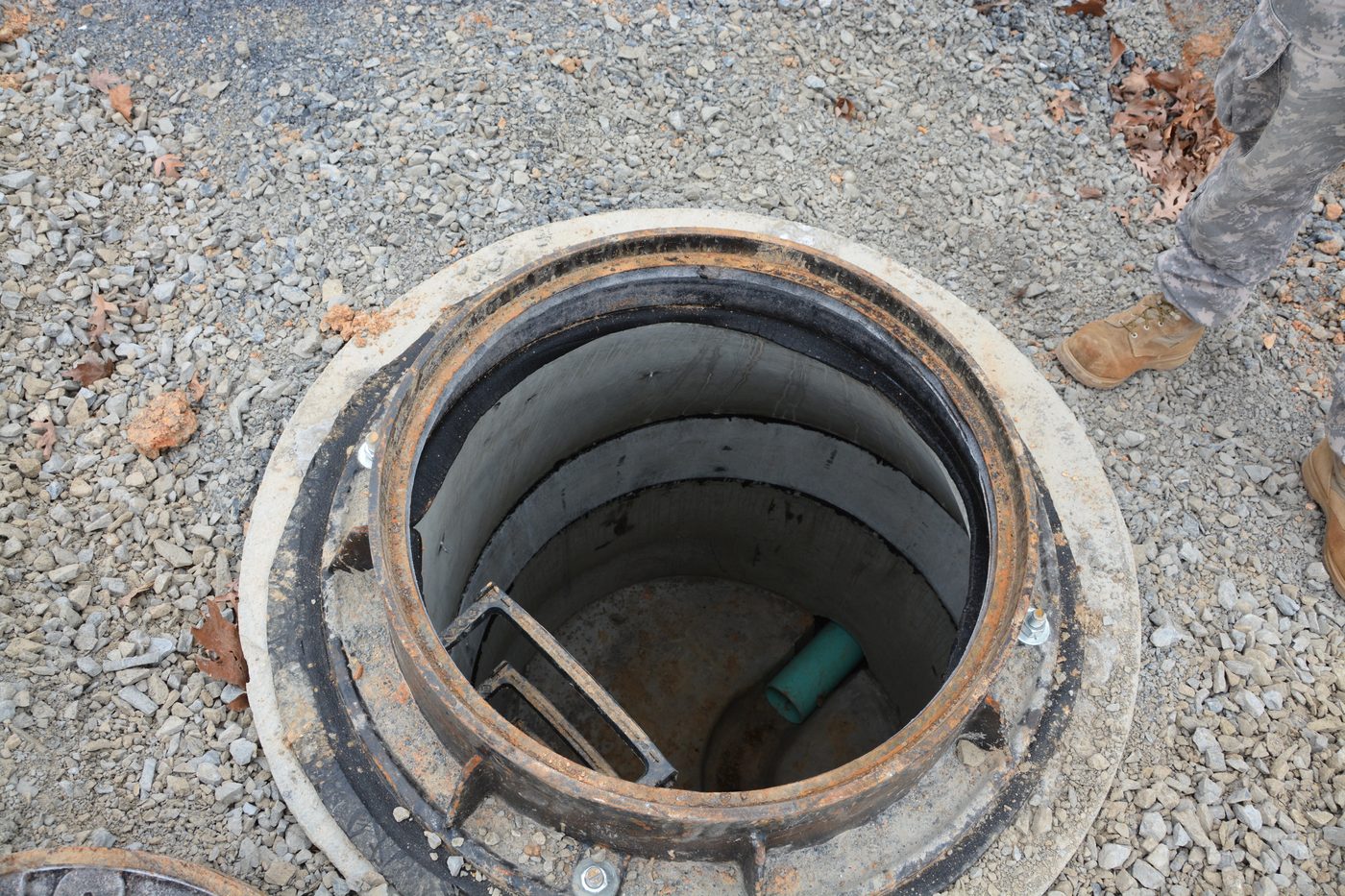
Open manhole with ladder and pipe inside (Source: Wikipedia (Sanitary manhole))
Pumping Stations: Facilities that lift wastewater when gravity flow is not feasible.
Outfalls: Points where treated or untreated wastewater is discharged into the environment.
In Nairobi County, the Nairobi City Water and Sewerage Company designs separate sewer systems with manholes every 90 meters to facilitate maintenance. The use of PVC pipes resistant to corrosion is standard to handle the acidic wastewater from industrial areas like Industrial Area Nairobi.
The cross-sectional area of wastewater pipes determines the volume of flow they can convey. Accurate sizing is essential to prevent overflows or blockages.
The cross-sectional area is the internal area through which wastewater flows, typically circular or rectangular in shape. It directly affects the hydraulic capacity and velocity of flow in the pipe or channel.
Designers must ensure the area accommodates peak flow rates with a safety margin to handle unexpected surges.
A larger cross-sectional area reduces velocity for a given flow, which can lead to sedimentation if too low. Conversely, a small area increases velocity but may cause erosion or pipe damage.
In Mombasa County, where tidal influences affect wastewater discharge, cross-sectional areas are designed with consideration for backflow prevention and sediment transport during low flow periods.
The slope of sewer lines influences the gravitational flow velocity and self-cleansing ability of the system.
Slope is the vertical drop per unit length of the sewer line, often expressed as a percentage or ratio (e.g., 0.5%).
Adequate slope ensures wastewater flows at velocities preventing solids from settling. Too steep a slope causes high velocities that may erode pipes, while too flat a slope leads to blockages.
Minimum slope is calculated based on pipe diameter and roughness to maintain a velocity of at least 0.6 m/s for self-cleansing. Maximum slope is constrained by structural and erosion concerns.
At the Kisumu County wastewater project, slopes are designed between 0.3% and 2% to balance flow efficiency and pipe longevity, considering soft soils prone to erosion.
The wetted perimeter is the length of the pipe or channel boundary in contact with the flowing wastewater.
It affects flow resistance and hydraulic radius, which in turn influence velocity and energy losses.
For circular pipes flowing partially full, wetted perimeter varies with flow depth and must be calculated using geometric relationships.
Hydraulic radius is the ratio of cross-sectional area to wetted perimeter; a larger hydraulic radius reduces friction losses, improving flow efficiency.
In Nairobi's sewer rehabilitation projects, detailed flow measurements allow precise wetted perimeter calculations to optimize pipe replacement sizes and reduce pumping costs.
Depth refers to the vertical distance from the ground surface to the invert (bottom) of the sewer pipe.
Depth affects hydraulic pressure, accessibility for maintenance, and protection from external loads such as traffic.
Minimum depth ensures pipes remain below frost lines and surface activities; maximum depth is limited by construction feasibility and cost.
Deeper pipes require stronger materials or thicker walls to withstand soil and live loads.
In Nairobi's central business district, deep sewers up to 6 meters are common to avoid utilities, requiring concrete pipes with reinforced walls.
Pipe diameter is a fundamental design parameter influencing flow capacity and velocity.
Diameter selection is based on peak flow rates, slope, and desired velocity to prevent sedimentation or erosion.
Common diameters range from 100 mm for household laterals to over 1500 mm for trunk sewers, using materials such as PVC, concrete, or ductile iron.
Larger diameters reduce clogging but increase construction costs; optimal sizing balances lifecycle costs.
The Kisumu wastewater treatment upgrade involved installing 600 mm diameter concrete pipes to handle increased industrial discharges.
Width is relevant mainly in open channels or rectangular conduits within wastewater infrastructure.
Width, combined with depth, defines the cross-sectional area and flow characteristics.
Width must accommodate expected flow volumes while maintaining velocities to avoid sedimentation.
Concrete or lined channels are preferred in urban wastewater systems for durability and ease of maintenance.
At Moi Teaching and Referral Hospital, open lined channels with widths of 0.5 to 1 meter are used for stormwater diversion, preventing contamination of wastewater streams.
Discharge is the volume of wastewater flowing through a section per unit time, typically expressed in cubic meters per second (m³/s).
Accurate discharge estimation is essential for sizing pipes and treatment facilities to prevent overflow and environmental pollution.
Population density, water usage patterns, industrial activities, and infiltration/inflow affect discharge volumes.
Flow meters and weirs are used in Kenyan urban areas to monitor discharge rates for operational control and regulatory compliance.
Design must incorporate provisions for peak flow events, such as rain-induced surges, to maintain system integrity.
Velocity is the speed at which wastewater moves through pipes or channels, usually in meters per second (m/s).
A velocity between 0.6 m/s and 3 m/s is generally targeted to prevent sediment deposition and pipe erosion.
Velocity is calculated using the formula: Velocity = Discharge / Cross-sectional Area
Low velocities lead to sediment buildup requiring frequent cleaning, while high velocities can damage infrastructure.
In Eldoret town, velocity control is emphasized in sewer design to minimize blockages caused by organic solids common in domestic wastewater.
Wastewater tunnels are subjected to various loads that affect their design and durability.
Tunnel linings must be designed to resist these loads using reinforced concrete or segmental linings.
Common failure modes include cracking, deformation, and water ingress, which compromise tunnel integrity.
The Nairobi Metro Sewage Tunnel project incorporates concrete segmental linings designed to withstand heavy traffic loads and groundwater pressures typical in the region.
Treatment facilities process wastewater to remove contaminants before disposal or reuse.
Include hydraulic loading rates, retention times, and sludge management.
Facilities must meet Kenya's Environmental Management and Coordination Act (EMCA) effluent standards to protect water bodies.
The Athi River Water Services Board operates a treatment plant using activated sludge technology to serve the rapidly growing Machakos area.
Slope within treatment facilities influences flow distribution and sedimentation efficiency.
Proper slope ensures settled solids slide toward collection points without resuspension.
Channels must have minimal slopes to allow controlled flow velocities for effective treatment.
Slope design must balance hydraulic needs with structural stability.
At Kisumu Wastewater Treatment Plant, settling tanks are designed with slopes of 1-2% to facilitate sludge removal.
Treatment infrastructure is exposed to mechanical and chemical forces that can cause failure.
Include pressure from flow, equipment vibrations, and sediment loading.
Corrosion from hydrogen sulfide and acidic conditions degrade concrete and metal structures.
Cracking, corrosion, clogging, and structural collapse.
Use of corrosion-resistant materials, regular maintenance, and structural monitoring.
Retention time is the duration wastewater remains in a treatment unit, critical for effective contaminant removal.
Calculated as volume of the treatment unit divided by the flow rate.
Vary by treatment type; for example, 2-4 hours for primary sedimentation, 6-8 hours for biological treatment.
Insufficient retention reduces contaminant removal; excessive retention increases costs and footprint.
In Nairobi's Dandora treatment works, retention times are optimized to handle fluctuating wastewater volumes from informal settlements.
Proper disposal of treated wastewater is essential to protect public health and the environment.
Infiltration Basins: Allowing percolation into groundwater.
Ocean Outfalls: Used in coastal cities with strict environmental controls.
Disposal methods must comply with Kenya's Water Act and EMCA to prevent pollution.
Include effluent quality, land availability, and proximity to water bodies.
In Nakuru County, treated effluent is reused for irrigation by flower farms, promoting water conservation and economic benefits.
Explain the key differences between separate and combined wastewater collection systems and their implications for design in Kenyan urban areas. (10 marks)
Calculate the cross-sectional area of a circular sewer pipe with a diameter of 500 mm. Show all steps. (5 marks)
Discuss the importance of slope in wastewater pipe design and how it affects flow velocity and self-cleansing. (8 marks)
Identify and explain five types of loads acting on wastewater tunnels and how these influence structural design. (12 marks)
Describe three common methods of treated wastewater disposal in Kenya and the factors influencing their selection. (10 marks)
Create a free account to open more of this chapter.
Free: practical guides, quick cards, workplace scenarios and more.
Create a free accountThis chapter focused on the essential parameters involved in designing wastewater infrastructure, covering key elements such as the collection system, cross-sectional area, slope, wetted perimeter, depth, diameter, width, discharge, velocity, and the loads experienced by tunnels. It also examined critical aspects of treatment facilities, including slope, forces and failure modes, retention time, and disposal methods. The discussion then shifted to construction materials, detailing the various materials and supplies required such as coarse and fine aggregates, cement, water, steel bars, timber, iron sheets, conduits, steel sheets, damp-proof courses, paints, varnishes, ceiling boards, wire mesh, construction stones and blocks, nails, as well as valves, pipes, and pipe fittings. Finally, the chapter emphasized the importance of engineering drawings in accurately conveying the design and specifications for wastewater infrastructure projects. Through these topics, the chapter provided a comprehensive overview of the technical specifications necessary for effective wastewater infrastructure design.
Type: Individual
| Tools & Equipment | Materials |
|---|---|
| Scientific Calculator | PPE (Overall, Safety Boots, Gloves) |
| 5 m Tape Measure | |
| Notebook and Pen | |
| Manila String | |
| Pegs |
| S/N | Item | Quantity |
|---|---|---|
| 1 | Scientific Calculator | 1 Pc per Candidate |
| 2 | 5 m Tape Measure | 1 Pc per Candidate |
| 3 | Notebook and Pen | 1 Pc each per Candidate |
| 4 | PPE (Overall, Safety Boots, Gloves) | 1 Set per Candidate |
| 5 | Manila String | 1 Pc per Candidate |
| 6 | Pegs | 4 Pcs per Candidate |
| Items to be Evaluated | Marks Available | Marks Obtained | Comments |
|---|---|---|---|
| TASK 1: Safety and Preparation | |||
| Wore PPE (Overall, Safety boots, Gloves) (Award 3 marks or zero) | 3 | ||
| Used tools and equipment correctly (Award 2 marks or zero) | 2 | ||
| Sub-Total | 5 | ||
| TASK 2: Measurement and Data Recording | |||
| Measured pipe diameter accurately (600mm ±2mm tolerance) (Award 3 marks or zero) | 3 | ||
| Recorded measurements correctly in notebook (Award 2 marks or zero) | 2 | ||
| Sub-Total | 5 | ||
| TASK 3: Hydraulic Parameter Calculations | |||
| Calculated cross-sectional area for half-full flow correctly (Award 6 marks or zero) | 6 | ||
| Calculated wetted perimeter correctly (Award 4 marks or zero) | 4 | ||
| Calculated hydraulic radius correctly (Award 4 marks or zero) | 4 | ||
| Calculated discharge using given flow velocity or formula (Award 6 marks or zero) | 6 | ||
| Calculated flow velocity correctly (Award 4 marks or zero) | 4 | ||
| Sub-Total | 24 | ||
| PRODUCT CHECKLIST | |||
| Cross-sectional area within ±5% of correct value for half-full 600mm pipe (Award 5 marks or zero) | 5 | ||
| Wetted perimeter within ±5% of correct value (Award 4 marks or zero) | 4 | ||
| Hydraulic radius within ±5% of correct value (Award 4 marks or zero) | 4 | ||
| Discharge calculated and verified as per formula with correct units (Award 6 marks or zero) | 6 | ||
| Velocity calculation verified and consistent with discharge and cross-section (Award 6 marks or zero) | 6 | ||
| Sub-Total | 25 | ||
| GRAND TOTAL | 59 | ||
Type: Individual
| Tools & Equipment | Materials |
|---|---|
| Scientific Calculator | |
| 5 m Tape Measure | |
| Manila String | |
| Wooden Pegs | |
| Slope Level | |
| Notebook and Pen |
| S/N | Item | Quantity |
|---|---|---|
| 1 | Scientific Calculator | 1 Pc per Candidate |
| 2 | 5 m Tape Measure | 1 Pc per Candidate |
| 3 | Manila String | 1 Pc per Candidate |
| 4 | Wooden Pegs | 6 Pcs per Candidate |
| 5 | Notebook and Pen | 1 Set per Candidate |
| 6 | PPE (Overall, Safety Boots, Gloves) | 1 Set per Candidate |
| 7 | Slope Level (Spirit Level or Laser Level) | 1 Pc per 3 Candidates |
| Items to be Evaluated | Marks Available | Marks Obtained | Comments |
|---|---|---|---|
| TASK 1: Safety and Preparation | |||
| Wore PPE (Overall, Safety boots, Gloves) (Award 3 marks or zero) | 3 | ||
| Prepared working area and arranged tools/materials (Award 2 marks or zero) | 2 | ||
| Sub-Total | 5 | ||
| TASK 2: Layout and Setting Out | |||
| Set out pipeline length of 100m accurately using tape measure and pegs (Award 4 marks or zero) | 4 | ||
| Used manila string to mark pipeline alignment (Award 3 marks or zero) | 3 | ||
| Established pipe slope of minimum 1% using slope level (Award 4 marks or zero) | 4 | ||
| Sub-Total | 11 | ||
| TASK 3: Hydraulic Design Specification | |||
| Calculated minimum and maximum flow velocity (0.6m/s to 3m/s) (Award 4 marks or zero) | 4 | ||
| Specified pipe diameter as 150mm (Award 3 marks or zero) | 3 | ||
| Determined discharge capacity based on estimated flow (Award 3 marks or zero) | 3 | ||
| Sub-Total | 10 | ||
| TASK 4: Documentation and Presentation | |||
| Prepared clear layout plan sketch with dimensions and slope (Award 4 marks or zero) | 4 | ||
| Recorded design parameters and calculations in notebook (Award 3 marks or zero) | 3 | ||
| Presented specifications clearly and logically (Award 3 marks or zero) | 3 | ||
| Sub-Total | 10 | ||
| PRODUCT CHECKLIST | |||
| Layout plan shows 100m pipeline with 150mm diameter pipes (Award 5 marks or zero) | 5 | ||
| Pipeline slope correctly specified as minimum 1% (Award 4 marks or zero) | 4 | ||
| Flow velocity calculations correct and within 0.6m/s to 3m/s (Award 5 marks or zero) | 5 | ||
| Discharge capacity specification consistent with design (Award 4 marks or zero) | 4 | ||
| Sub-Total | 18 | ||
| GRAND TOTAL | 54 | ||
At the start of this chapter we promised you would be able to:
Tick each one you can genuinely do.
So, are you there yet?
You're competent when you can confidently do 50% or more of what this chapter promised.
Sign in to record how you're doing.