Building drawings are essential tools for communication among architects, structural engineers, contractors, and site supervisors involved in building projects. Structural drawings, in particular, detail the framework that supports the building, ensuring safety, stability, and compliance with Kenya’s building codes. This chapter focuses on preparing structural drawings, emphasizing the key structural elements that form the backbone of any building project in the Kenyan context. Mastery of these drawings enhances accurate construction, reduces risks, and facilitates professional coordination on site.
2.1 Structural elements
Structural elements are the primary components that transfer loads safely to the ground, maintaining the building’s integrity and stability. In Kenya, understanding these elements is crucial for professionals working on commercial buildings, residential complexes, and public infrastructure projects. Structural drawings must clearly depict these elements with correct dimensions, reinforcement details, and specifications to guide construction teams effectively.
2.1.1 Beams
Beams are horizontal structural members designed to carry and transfer loads from slabs, walls, and roofs to columns or walls. They resist bending forces and shear stresses, playing a vital role in supporting floors and roofs in buildings across Kenya.
Types of beams commonly used in building construction
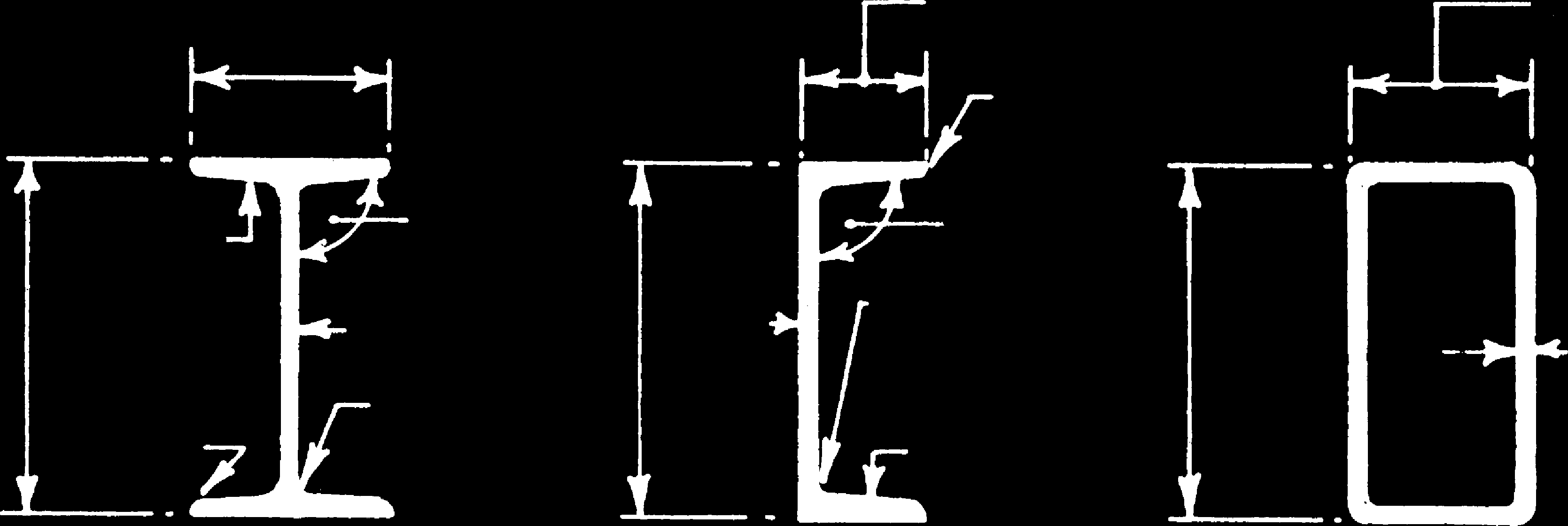
Technical drawings of three different steel beam cross-sections (I-bea (Source: Chudley)
- Simply supported beams: These rest on supports at both ends and carry loads between supports. They are widely used in small to medium-span floor systems in schools and retail outlets.

A simply supported beam (Source: STRUCTURES I-DBT-MOD I)
- Cantilever beams: Fixed at one end and free at the other, they are used for balconies and overhangs in hotels and residential buildings.
- Continuous beams: Extend over more than two supports, common in multi-storey buildings such as county government offices for enhanced load distribution.
- Fixed beams: Both ends are fixed to supports, providing higher resistance to bending moments, often used in structural frames of commercial buildings.
- T-beams: Formed by the slab and beam acting together, providing an efficient load path in reinforced concrete floor systems in hospitals.
Materials used for beams and their selection criteria
- Reinforced concrete: Preferred for its high compressive strength and durability in Kenya’s varied climate; suitable for most building types.
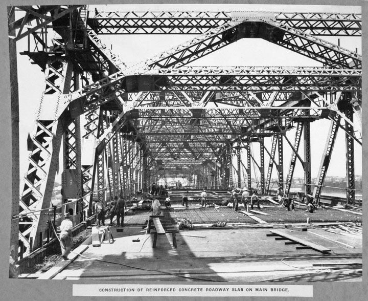
Construction of reinforced concrete roadway slab (Source: Wikimedia Commons)
-
Steel beams: Used where high tensile strength and lighter weight are required, such as in industrial warehouses.
-
Timber beams: Common in low-cost housing and rural constructions due to availability and ease of handling.

timber beams supporting building entrance roof (Source: Wikimedia Commons)
- Composite beams: Combine steel and concrete for enhanced performance in large-span structures like university halls.
- Pre-stressed concrete beams: Used in bridges and large commercial buildings for superior strength and reduced deflection.
Standard drawing conventions for beams
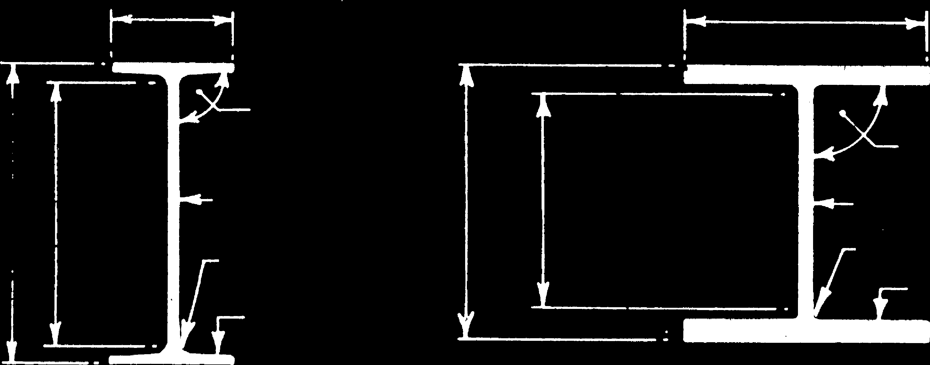
Cross-sectional diagrams of two types of steel beams (Source: Chudley)
- Line types: Continuous thick lines for beam outlines, dashed lines for hidden reinforcement or embedded parts.
- Dimensions: Length, width, and depth clearly indicated in millimeters, with reinforcement spacing and bar diameters specified.
- Symbols: Use of standard symbols for stirrups, main reinforcement bars, and concrete cover as per British Standard BS 8666.
- Scale: Typically drawn at 1:20 or 1:50 depending on complexity and sheet size.
- Title block: Includes beam designation, project details, drawing number, and revision history.
Procedure for drawing a reinforced concrete beam
- Draw the beam outline to scale using continuous thick lines.
- Indicate beam length, width, and depth with clear dimension lines.
- Add the main reinforcement bars along the beam’s length, showing bar diameter and spacing.
- Draw stirrups (shear reinforcement) with appropriate spacing and bar sizes.
- Specify concrete cover distance from the outer surface to reinforcement.
- Include notes on concrete grade and steel specifications.
Practice Questions
- Draw a simply supported reinforced concrete beam of 4m span, 300mm width, and 500mm depth showing main reinforcement and stirrups. (15 marks)
- Explain the differences between cantilever and continuous beams with examples from building structures. (10 marks)
2.1.2 Columns
Columns transfer compressive loads from slabs and beams down to foundations, ensuring vertical support and stability in buildings. Structural drawings for columns in Kenya must accurately show dimensions, reinforcement, and connection details to withstand axial loads and bending moments.
Types of columns used in building construction
- Rectangular columns: Most common type, easy to construct and suitable for most building layouts.
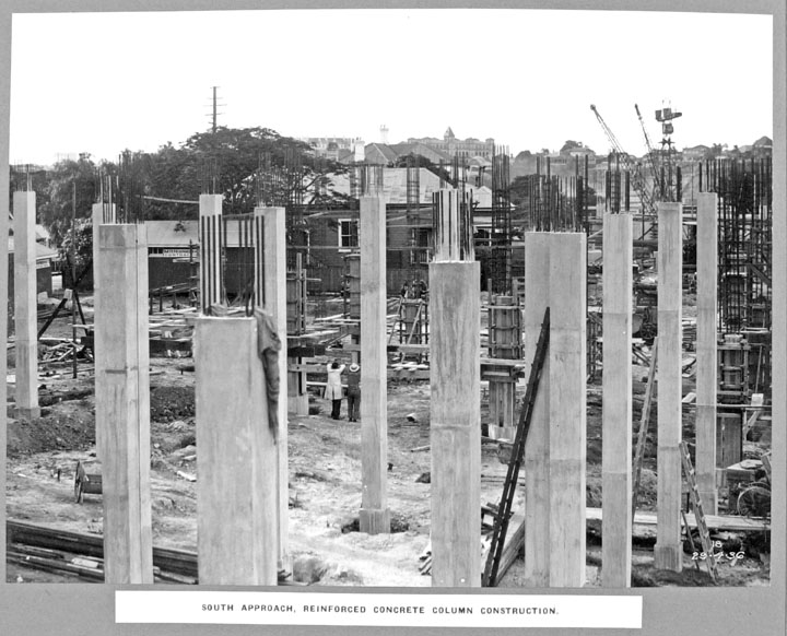
Reinforced concrete rectangular columns under construction (Source: Wikimedia Commons)
-
Circular columns: Provide uniform strength in all directions and are used in aesthetic architectural designs.
-
L-shaped columns: Used at building corners where two walls intersect, providing combined support.
- Composite columns: Made from steel encased in concrete, used in high-rise buildings for enhanced load capacity.
- Fluted columns: Mainly decorative but can also serve structural functions in public buildings.
Reinforcement detailing in columns
-
Longitudinal bars: Vertical bars running the length of the column, typically 4 to 8 bars depending on load.
-
Ties or hoops: Circular or rectangular stirrups that hold longitudinal bars in place and resist shear.
- Concrete cover: Minimum cover requirement of 40mm in Kenya to protect reinforcement from corrosion.
- Lap splices: Overlapping of bars to provide continuity where bars are cut.
- Column base: Details showing connection to foundation, including base plate or reinforcement anchorage.
Drawing standards for columns
- Line thickness: Thick continuous lines for column edges, thinner lines for reinforcement.
- Reinforcement symbols: Standardized symbols for bars and ties as per BS 8666.
- Dimensioning: Width and depth of columns shown on plan and elevation views.
- Section views: Cross-section drawings clearly indicating reinforcement layout.
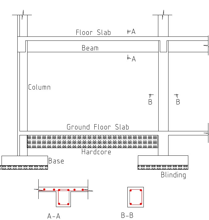
A structural section of a building (Source: Design engineering structures)
- Notes: Concrete strength, bar grades, and construction sequence instructions.
Steps to prepare a column structural drawing
- Draw the column outline in plan view at correct scale.
- Add elevation view showing column height and section dimensions.
- Insert longitudinal reinforcement bars with correct spacing and diameter.
- Draw ties or hoops around longitudinal bars with spacing details.
- Specify concrete cover and lap splice lengths.
- Include annotations on concrete grade and steel specification.
Practice Questions
- Prepare a structural drawing for a rectangular column 400mm by 400mm with 6 longitudinal bars and 10mm ties at 150mm centers. (15 marks)
- Describe the purpose and detailing of ties in column reinforcement. (10 marks)
2.1.3 Stairs
Stairs provide vertical circulation between floors and must be structurally sound and safe. Structural drawings for stairs in Kenya require precise depiction of treads, risers, stringers, and reinforcement to ensure compliance with building regulations.
Components of staircases
-
Treads: Horizontal surfaces where users step, typically 250mm deep.
-
Risers: Vertical faces between treads, usually 150mm high.
-
Stringers: Structural members supporting the treads and risers on either side.
-
Landing: Flat platforms between flights for rest and change of direction.

Rusty metal staircase landing platform (Source: Wikimedia Commons)
- Handrails and balustrades: Safety features often detailed separately but coordinated with structural elements.
Types of staircases commonly used
- Straight stairs: Simplest form, suitable for small buildings such as retail shops.
- L-shaped stairs: Change direction at a landing, common in offices and schools.
- Spiral stairs: Compact design used in limited spaces, such as in cooperatives’ offices.
- Dog-legged stairs: Two flights parallel but opposite directions with a landing in between.
- Curved stairs: Architecturally appealing, used in hotels and upscale residential buildings.
Structural drawing conventions for stairs
- Plan view: Shows tread and riser arrangement, flight length, and landing dimensions.
- Section view: Indicates stair slope, reinforcement in treads and risers, and stringer details.
- Reinforcement: Main bars along stringers and distribution bars in treads.
- Symbols: Use standard notation for bars, concrete cover, and dimensions.
- Scales: Typically 1:20 or 1:50 depending on detail level.
Procedure to draw a reinforced concrete stair
- Draw stair outline in plan showing all flights and landings.
- Indicate tread depth and riser height dimensions.
- Add section view illustrating slope and reinforcement placement.
- Detail main reinforcement bars along stringers with size and spacing.
- Include distribution reinforcement in treads and risers.
- Specify concrete cover, bar grades, and notes on construction sequence.
Practice Questions
- Draw a plan and section of an L-shaped reinforced concrete stair with 150mm risers and 250mm treads. (15 marks)
- Explain the role of stringers in stair structural design. (10 marks)
2.1.4 Foundation
Foundations transfer the building load safely to the ground, preventing settlement and structural failure. In Kenya, foundation design and drawings must consider soil conditions, load types, and building use.
Types of foundations used in Kenya
- Strip foundations: Continuous strips under load-bearing walls, common in residential buildings.
-
Isolated pad foundations: Individual footings for columns, used in commercial and institutional buildings.
-
Raft foundations: Large slabs supporting entire building footprint, applied in poor soil conditions such as in Nairobi’s soft soils.
-
Pile foundations: Deep foundation using long columns driven into the ground, for heavy structures like hospitals.
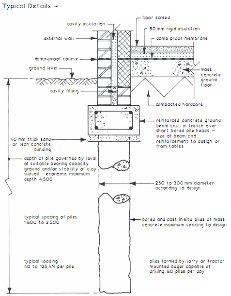
A detailed cross-section of a typical reinforced concrete pile foundat (Source: substructure-1)
- Combined foundations: Footings shared by two or more columns, used where columns are closely spaced.
Factors influencing foundation selection
- Soil bearing capacity: Determines type and size of foundation; soil tests are mandatory.
- Load magnitude: Heavier buildings require deeper or more robust foundations.
- Water table level: High water tables may necessitate special foundation types.
- Building use: Public buildings require more stringent foundation design.
- Cost and availability: Budget and local materials impact foundation choice.
Drawing standards for foundation plans
- Plan view: Shows foundation layout, footing sizes, and column positions.
- Section view: Indicates footing depth, reinforcement, and ground level.
- Reinforcement: Detailed bar sizes and spacing for footings.
- Dimensions: Clear indication of footing length, width, and depth in millimeters.
- Notes: Include soil bearing capacity, concrete mix, and construction instructions.
Steps to prepare structural foundation drawings
- Obtain soil test reports to determine bearing capacity.
- Draw foundation plan showing all footings aligned with columns.
- Add dimensions for footing length, width, and spacing.
- Prepare section views showing footing depth and reinforcement layout.
- Detail reinforcement bars with diameters and spacing.
- Include notes on concrete grade, curing time, and excavation requirements.
Practice Questions
- Prepare a foundation plan and section for a strip footing supporting a load-bearing wall with dimensions 600mm wide and 1000mm deep. (15 marks)
- Discuss the factors that influence the choice of foundation type in building construction. (10 marks)
2.1.5 Slabs
Slabs form the floors and roofs of buildings, distributing loads to beams and columns. Accurate structural drawings for slabs are critical in Kenya to ensure durability and load-bearing capacity compliant with building regulations.
Types of slabs used in building construction
-
One-way slabs: Supported on two opposite sides, transferring loads in one direction; common in small residential buildings.
-
Two-way slabs: Supported on all four sides, distributing loads in two directions; used in multi-storey buildings such as banks.
- Flat slabs: Supported directly on columns without beams, allowing flexible column placement in offices.
- Ribbed slabs: Consist of ribs running in one direction beneath a thin slab; used in large floor areas like university lecture halls.
- Hollow core slabs: Precast slabs with voids to reduce weight, increasingly used in commercial buildings.
Reinforcement detailing in slabs
- Main reinforcement: Bars placed in the direction of maximum bending moment.
- Distribution bars: Perpendicular to main bars to distribute loads evenly.
- Concrete cover: Minimum 25mm to protect reinforcement from corrosion.
- Shear reinforcement: Provided in areas of high shear stress, such as slab edges.
- Control joints: Incorporated to prevent cracking due to shrinkage and temperature changes.
Drawing conventions for slabs
- Plan view: Shows slab outline, thickness, and reinforcement layout.
- Section view: Indicates slab thickness, reinforcement positions, and support details.
- Symbols: Standard symbols for main and distribution reinforcement bars.
- Dimensions: Thickness, bar spacing, and slab span shown in millimeters.
- Notes: Concrete grade, curing instructions, and load specifications.
Procedure for preparing slab structural drawings
- Draw the slab outline in plan view with dimensions.
- Indicate slab thickness and support positions.
- Layout main reinforcement bars with size and spacing.
- Add distribution reinforcement bars perpendicular to main bars.
- Show section views with slab thickness and reinforcement cover.
- Include notes on concrete mix, curing, and load-bearing capacity.
Practice Questions
- Draw a two-way slab plan and section with 150mm thickness, showing main and distribution reinforcement spaced at 200mm centers. (15 marks)
- Explain the difference between one-way and two-way slabs with examples of their use. (10 marks)
The rest of this chapter
🔒Create a free account to open more of this chapter.
Free: practical guides, quick cards, workplace scenarios and more.
Create a free account 🔒2.2 Codes of practice
In the Kenyan building industry, adherence to codes of practice is crucial for ensuring construction safety, durability, and regulatory compliance. Structural drawings must conform to established standards and guidelines that govern design, materials, and work…
🔒2.3 Bar bending schedule
The bar bending schedule (BBS) is an essential document accompanying structural drawings, specifying detailed reinforcement bar information. In Kenya, BBS preparation is critical for accurate material estimation, cost control, and ensuring structural integrity…
🔒2.4 Detailed plans and sections
The design of detailed structural plans and sections involves translating structural calculations and architectural layouts into clear, standardized drawings that guide construction. The design process must incorporate Kenya’s building regulations, material sp…
Chapter Summary
This chapter covered the preparation of structural drawings by first examining key structural elements such as beams, columns, stairs, foundations, and slabs, highlighting their roles and representation in drawings. It emphasized adherence to relevant codes of practice to ensure safety, quality, and compliance with Kenyan and international standards. The importance of the bar bending schedule was detailed, showing how it guides the cutting and bending of reinforcement bars accurately. The chapter also explained how to develop detailed plans and sections, focusing on clear, precise, and scaled representations that communicate the design intent effectively. The design aspect was integrated to demonstrate how structural elements are dimensioned and arranged to meet functional and load-bearing requirements. Overall, the chapter provided a comprehensive approach to producing structural drawings that are accurate, standardized, and practical for construction use.
Self-Assessment
🔒 PDFDownload this self-assessment, with answers
A. Written Assessment
-
Which of the following is NOT a primary function of a beam in building construction?
a) Support vertical loads
b) Resist lateral wind forces
c) Transfer loads to columns
d) Span between supports
(2 marks)
-
Describe the key differences between short columns and long columns in structural design. (3 marks)
🔒28 more in this section.
Chapter Examination Questions
🔒 PDFDownload these examination questions, with worked answers
SECTION A (40 Marks) - Answer ALL Questions
- Outline THREE purposes of architectural drawings in a building project. (4 marks)
- List FOUR key elements that must be included in structural drawings. (4 marks)
🔒18 more in this section.
Chapter Practical Activities
Practical 1: Identify and Label Structural Elements on a Beam Drawing
Building Technology · Level 6
Building Drawings
PRACTICAL ASSESSMENT
TIME: 4 HOURS
⬇ PDFCandidate Instructions (Candidate Tool)
Type: Individual
INSTRUCTIONS TO CANDIDATE:
1. You are required to perform the following task:
i. Identify and label all structural elements on a 4000mm x 300mm x 500mm reinforced concrete beam drawing as per the provided working drawing.
2. You have been provided with the following resources for the practical task:
| Tools & Equipment | Materials |
|---|
| Computer installed with AutoCAD software | A3 paper Size |
| Printer | A4 paper Size |
⬇ PDFResources Required (Cutting List)
| S/N | Item | Quantity |
|---|
| 1 | Computer installed with AutoCAD software | 1 Pc per Candidate |
| 2 | A3 paper Size | 2 Pcs per Candidate |
| 3 | A4 paper Size | 1 Pc per Candidate |
| 4 | Printer | 1 Pc per 30 Candidates |
⬇ PDFAssessor Guide
| Items to be Evaluated | Marks Available | Marks Obtained | Comments |
|---|
| TASK 1: Identification and Labelling of Structural Elements |
Wore appropriate PPE before commencing work
(Award 1 mark for correct PPE use or zero) | 1 | | |
Opened the provided working drawing file correctly
(Award 1 mark for correct file opening or zero) | 1 | | |
Set the drawing scale to 1:50 as per instructions
(Award 2 marks for correct scale setting or zero) | 2 | | |
Identified the beam element on the drawing accurately
(Award up to 3 marks for correct identification or zero) | 3 | | |
Labelled the main reinforcement bars (4Y20) correctly on the beam
(Award up to 3 marks for correct labelling or zero) | 3 | | |
Labelled the shear links (R10 @ 150 c/c) correctly
(Award up to 3 marks for correct labelling or zero) | 3 | | |
Labelled the beam dimensions (length, width, depth) clearly
(Award 2 marks for clear dimension labelling or zero) | 2 | | |
Followed relevant Kenya Building Codes for labelling conventions
(Award up to 3 marks for adherence or zero) | 3 | | |
Saved the labelled drawing as PDF in the specified folder
(Award 1 mark for correct saving or zero) | 1 | | |
Printed the labelled drawing on A3 sheet without errors
(Award 2 marks for correct printing or zero) | 2 | | |
| Sub-Total | 21 | | |
| PRODUCT CHECKLIST |
Labels accurately placed and clearly visible on the beam drawing
(Award 5 marks for clear and correct labelling or zero) | 5 | | |
Beam dimensions correctly labelled as 4000mm length x 300mm width x 500mm depth
(Award 4 marks for correct dimension labelling or zero) | 4 | | |
Labelling follows Kenya Building Code standards for structural drawings
(Award 5 marks for compliance or zero) | 5 | | |
| Sub-Total | 14 | | |
| GRAND TOTAL | 35 | | |
ASSESSMENT OUTCOME: ☐ Competent ☐ Not Yet Competent (competent if at least 50%)
Practical 2: Prepare detailed structural drawing for a reinforced concrete beam
Building Technology · Level 6
Building Drawings
PRACTICAL ASSESSMENT
TIME: 4 HOURS
⬇ PDFCandidate Instructions (Candidate Tool)
Type: Individual
INSTRUCTIONS TO CANDIDATE:
1. You are required to perform the following task:
i. Prepare a detailed structural drawing of a reinforced concrete beam 4000mm long, 300mm wide, and 500mm deep as per the provided working drawing.
2. You have been provided with the following resources for the practical task:
| Tools & Equipment | Materials |
|---|
| Computer installed with AutoCAD software | A3 paper Size |
| Printer | A4 paper Size |
⬇ PDFResources Required (Cutting List)
| S/N | Item | Quantity |
|---|
| 1 | Computer installed with AutoCAD software | 1 Pc per Candidate |
| 2 | A3 paper Size | 2 Pcs per Candidate |
| 3 | A4 paper Size | 1 Pc per Candidate |
| 4 | Printer | 1 Pc per 30 Candidates |
⬇ PDFAssessor Guide
| Items to be Evaluated | Marks Available | Marks Obtained | Comments |
|---|
| TASK 1: Prepare beam structural drawing |
Wore appropriate PPE before starting work
(Award 1 mark for correct PPE usage or zero) | 1 | | |
Set the drawing scale to 1:20 as per working instructions
(Award 2 marks for correct scale set, zero if incorrect) | 2 | | |
Drew the beam outline with correct external dimensions (4000mm x 300mm x 500mm)
(Award 3 marks for accurate beam outline, zero if dimensions incorrect) | 3 | | |
Added detailed reinforcement main bars (4Y20) as per specification
(Award 3 marks for correct number and size of main bars, zero if incorrect) | 3 | | |
Drew stirrups (R10 links) spaced at 150mm c/c along the beam length
(Award 3 marks for correct stirrup size and spacing, zero if incorrect) | 3 | | |
Added sectional views showing beam depth and reinforcement placement
(Award 3 marks for clear and accurate sections, zero if missing or inaccurate) | 3 | | |
Lettered and annotated the drawing correctly with materials and bar sizes
(Award 2 marks for clear lettering and correct annotations, zero if missing) | 2 | | |
Dimensioned the beam plan and sections fully and accurately
(Award 3 marks for complete and correct dimensioning, zero if incomplete) | 3 | | |
Opened A3 layout and placed the drawing correctly with margins set
(Award 2 marks for correct layout setup and margin settings, zero if incorrect) | 2 | | |
Saved the drawing in PDF format with correct file naming
(Award 1 mark for saved PDF correctly, zero if missing or wrong format) | 1 | | |
Printed the drawing on A3 paper clearly and legibly
(Award 2 marks for clear, legible print on A3 paper, zero if poor print) | 2 | | |
| Sub-Total | 25 | | |
| PRODUCT CHECKLIST |
Beam drawing external dimensions exactly 4000mm length, 300mm width, 500mm depth
(Award 5 marks if all dimensions match exactly, zero if any dimension is wrong) | 5 | | |
Reinforcement details: 4Y20 main bars and R10 stirrups at 150mm c/c correctly shown
(Award 5 marks for accurate reinforcement details, zero if incorrect) | 5 | | |
Sections clearly show reinforcement placement and beam depth
(Award 3 marks for accurate sectional views, zero if missing or unclear) | 3 | | |
Drawing is fully dimensioned, lettered, and annotated as per standards
(Award 4 marks for complete and professional annotations, zero if incomplete) | 4 | | |
Drawing is neat, clear, and printed on A3 sheet without smudges or errors
(Award 3 marks for neatness and quality of print, zero if poor quality) | 3 | | |
| Sub-Total | 20 | | |
| GRAND TOTAL | 45 | | |
ASSESSMENT OUTCOME: ☐ Competent ☐ Not Yet Competent (competent if at least 50%)
🔒Prepare detailed structural drawing for a reinforced concrete columnPractical 3
🔒Draw detailed structural stair drawings including reinforcement layoutPractical 4
🔒Prepare detailed foundation structural drawingPractical 5
🔒Draw detailed slab structural plan and sectionsPractical 6
🔒Develop Bar Bending Schedule for a Reinforced Concrete Beam 4000mm x 300mm x 500mmPractical 7
🔒Design and Prepare Structural Drawing for a Reinforced Concrete BeamPractical 8
🔒Interpret and Verify Structural Drawing for a Reinforced Concrete BeamPractical 9
🔒Prepare a composite structural drawing integrating beams, columns, foundation, and slabsPractical 10
