Producing accurate solid geometry drawings is essential for automotive engineering technology professionals in Kenya, as these drawings form the basis for understanding complex automotive components and assemblies. Solid geometry drawings help technicians and engineers visualize, fabricate, and inspect parts such as engine cylinders, chassis components, and other three-dimensional structures. Mastery of sketching and drawing patterns for basic solids like cylinders, prisms, and pyramids is foundational for progressing to more complex automotive designs and ensuring precise manufacturing and assembly processes.
4.1 Sketches and Drawings of Patterns
This section focuses on developing skills to create sketches and technical drawings of fundamental solid shapes that are frequently encountered in automotive engineering components. Mastery of these shapes aids in visualizing parts during design, fabrication, and repair tasks in automotive workshops and manufacturing plants across Kenya.
4.1.1 Cylinders
Cylinders are among the most common solids in automotive engineering, appearing in engine components such as pistons, cylinders, and shafts. Understanding how to sketch and draw cylinders accurately allows technicians to interpret and communicate design specifications clearly.
Characteristics of Cylinders
- Curved Surface: Cylinders have one curved surface that is formed by revolving a rectangle around one of its sides, creating a circular cross-section.
- Two Parallel Circular Bases: The top and bottom faces are congruent circles lying in parallel planes.
- Height: The distance between the two circular bases is the height of the cylinder, critical for defining its size.
- Axis of Symmetry: A straight line passing through the centers of the two bases, defining the central axis of the cylinder.
- Right and Oblique Types: Right cylinders have bases aligned directly above each other, whereas oblique cylinders have bases offset, altering the shape.
Step-by-Step Procedure for Drawing a Cylinder
- Draw the Axis: Start by drawing a vertical centerline representing the axis of the cylinder.
- Draw the Base Ellipse: Sketch an ellipse at the bottom to represent the circular base in perspective.
- Mark the Height: Measure and mark the height along the axis line.
- Draw the Top Ellipse: Sketch another ellipse parallel to the base at the height mark.
- Connect the Ellipses: Draw two straight lines joining the corresponding edges of the ellipses to form the curved surface.
- Add Details and Dimensions: Include dimensions such as diameter, height, and any other relevant annotations for clarity.
Importance of Accurate Cylinder Drawings in Automotive Engineering
- Component Fit: Ensures parts such as pistons fit precisely within the cylinder bore, avoiding wear and performance issues.
- Manufacturing Guidance: Provides machinists with exact dimensions needed for fabrication.
- Assembly Instructions: Assists assembly technicians in aligning components correctly.
- Inspection References: Facilitates quality control through dimensional verification.
- Communication: Enhances clear technical communication among design, production, and maintenance teams.
Common Errors in Cylinder Drawings and How to Avoid Them
- Incorrect Ellipse Proportions: Ellipses should reflect the correct perspective; using guidelines helps maintain proportional accuracy.
- Misaligned Axes: Ensure the top and bottom ellipses share the same central axis for a right cylinder.
- Missing Dimensions: Omitting diameter or height leads to ambiguity; always label critical measurements.
- Overlapping Lines: Use proper line types to distinguish visible and hidden edges according to standards.
- Ignoring Standards: Follow BS EN ISO 128 or Kenya Bureau of Standards (KEBS) for line types and annotations.
4.1.2 Prisms
Prisms are solid shapes with two congruent polygonal bases connected by rectangular faces. They are common in automotive structures such as chassis members and brackets.
Types and Characteristics of Prisms
-
Right Prism: The sides are perpendicular to the bases, resulting in rectangular lateral faces.
-
Oblique Prism: The sides are not perpendicular, causing parallelogram lateral faces.
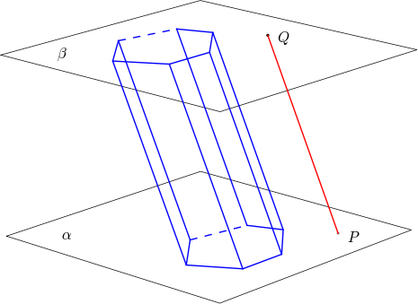
Oblique prism between two planes (Source: Wikimedia Commons)
- Bases: Can be any polygon such as triangles, rectangles, or hexagons.
- Edges and Faces: Number of lateral faces equals the number of edges in the base polygon.
- Uniform Cross-Section: The cross-section parallel to the bases remains constant along the height.
Procedure for Drawing a Right Prism
- Draw the Base Polygon: Sketch the base shape accurately using construction lines.
- Project Vertical Lines: From each vertex of the base, draw vertical lines to represent the prism’s height.
- Mark the Height: Decide and mark the height on each vertical line using a scale.
- Draw the Top Polygon: Connect the top points corresponding to the base vertices, forming the congruent top face.
- Draw Lateral Faces: Join corresponding vertices on the base and top polygons to form the lateral faces.
- Label Dimensions and Details: Include base side lengths, height, and any relevant annotations for clarity.
Significance of Prism Drawings in Automotive Engineering
- Structural Components: Prisms represent frame members and supports that require precise fabrication.
- Load Distribution: Understanding prism geometry helps in stress analysis of components.
- Manufacturing Accuracy: Guides cutting and welding processes for chassis and body parts.
- Assembly Fit: Ensures components align and fit within assemblies.
- Technical Communication: Provides clear visual references for engineers and workshop staff.
Standards and Conventions for Prism Drawings
- Line Types: Use continuous thick lines for visible edges and dashed lines for hidden edges as per BS 8888.
- Scale: Typical engineering drawing scales such as 1:1, 1:2, or 1:5 depending on object size.
- Title Block: Include drawing title-scale, drafter’s name, and date following KEBS guidelines.
- Dimensioning: Use aligned dimensioning with arrows and units in millimeters.
- Projection Method: First-angle projection is standard in Kenya, so ensure correct views.
4.1.3 Pyramids
Pyramids are solids with polygonal bases and triangular faces converging to a single apex. They appear in automotive design in components like certain types of brackets or decorative trims.
Characteristics of Pyramids
- Base Polygon: Can be any polygon, commonly triangular or square in automotive components.
- Apex: A single vertex not in the base plane, where all triangular faces meet.
- Triangular Faces: Number equals the number of sides on the base polygon.
- Height: The perpendicular distance from the apex to the base plane.
- Slant Edges: Edges connecting the apex to base vertices.
Drawing Procedure for a Square Pyramid
- Draw the Base Square: Sketch the base square accurately using construction lines.
- Find the Center: Mark the center point of the base, which helps locate the apex.
- Mark the Apex Height: Measure and mark the height perpendicular to the base center.
- Draw the Apex Point: Plot the apex above the base at the marked height.
- Connect Apex to Base Vertices: Draw straight lines from the apex to each vertex of the base.
- Add Dimensions and Annotations: Label base side length, height, and other necessary details.
Importance of Pyramid Drawings in Automotive Engineering
- Custom Brackets and Supports: Pyramidal shapes often appear in load-bearing brackets.
- Visualizing Complex Shapes: Helps technicians understand shape and volume for manufacturing.
- Stress Analysis: Assists in analyzing load paths through triangular faces.
- Fabrication Guidance: Provides clear instructions for cutting and welding sheet metal.
- Technical Documentation: Serves as part of design documentation for quality assurance.
Common Mistakes and How to Avoid Them in Pyramid Drawings
- Incorrect Apex Placement: Ensure apex is aligned properly above the base center for symmetrical pyramids.
- Distorted Base: Use precise construction methods to avoid irregular base polygons.
- Missing Dimensions: Always include base side lengths and height for complete specification.
- Poor Line Differentiation: Follow line type standards to distinguish visible and hidden edges.
- Ignoring Scale: Choose an appropriate scale to ensure clarity and accuracy.
Practice Questions
-
Draw a right circular cylinder with a diameter of 60 mm and a height of 100 mm using first-angle projection. Include all necessary dimensions and annotations. (15 marks)
-
Sketch a right triangular prism with a base triangle of sides 40 mm, 50 mm, and 60 mm, and a prism height of 80 mm. Label all dimensions. (15 marks)
-
Construct a square pyramid with a base side length of 70 mm and a height of 90 mm. Show all construction lines and label the drawing. (20 marks)
-
Explain the differences between right and oblique prisms, giving examples of where each might be used in automotive engineering. (10 marks)
The rest of this chapter
🔒Create a free account to open more of this chapter.
Free: practical guides, quick cards, workplace scenarios and more.
Create a free account 🔒4.2 Solids Drawings
In automotive engineering technology, the ability to produce accurate solid geometry drawings is essential for designing and understanding components such as engine parts, chassis elements, and fluid system fittings. Solid drawings provide a three-dimensional…
🔒4.3 Development and Interpenetrations of Solids
In automotive engineering design, understanding the development and interpenetrations of solids is critical for creating accurate technical drawings that represent complex components such as engine parts, exhaust systems, and chassis elements. Kenyan automotiv…
🔒4.4 Different symbols and abbreviations
In automotive engineering technical drawings, the correct use of symbols and abbreviations is crucial for clear communication among professionals. Kenya’s automotive workshops and manufacturing plants rely on standardized symbols to convey complex information…
🔒4.5 Auxiliary views and true shapes of truncated solids
Understanding auxiliary views and true shapes of truncated solids is essential for automotive engineers and technicians when interpreting or producing complex component drawings. Vehicles contain many parts such as truncated cylinders, prisms, and pyramids whe…
Chapter Summary
This chapter focused on producing solid geometry drawings, beginning with the sketches and drawings of common patterns such as cylinders, prisms, and pyramids. It progressed to detailed solid drawings of prisms, cones, and cylinders, emphasizing accurate representation and dimensioning. The development and interpenetration of solids were explored through practical cases involving cylinder to cylinder, cylinder to prism, and prism to prism intersections. Understanding and applying different symbols and abbreviations used in technical drawings ensured clarity and standardization. The chapter also covered the construction of auxiliary views and the true shapes of truncated solids, including truncated cylinders, prisms, and pyramids. Mastery of these concepts enables precise and professional technical drawings essential for engineering and manufacturing applications.
Self-Assessment
🔒 PDFDownload this self-assessment, with answers
A. Written Assessment
- What is the primary difference between a prism and a pyramid in solid geometry drawings? (2 marks)
- Identify the correct line type used to represent hidden edges in BS 8888 technical drawings. (1 mark)
🔒25 more in this section.
Chapter Examination Questions
🔒 PDFDownload these examination questions, with worked answers
SECTION A (40 Marks) - Answer ALL Questions
- Sketch the development pattern of a cylinder with a height of 80 mm and diameter of 40 mm used as a muffler casing in a Nairobi-based automotive workshop. (4 marks)
- Draw the front and top views of a triangular prism with a base of 60 mm and height 100 mm, representing a structural component in a vehicle chassis design. (4 marks)
🔒22 more in this section.
Chapter Practical Activities
Practical 1: Sketch and draw patterns of basic solid shapes
Automotive Engineering Technology · Level 5
Technical Drawing
PRACTICAL ASSESSMENT
TIME: 4 HOURS
⬇ PDFCandidate Instructions (Candidate Tool)
Type: Individual
INSTRUCTIONS TO CANDIDATE:
1. You are required to perform the following task:
i. Sketch and draw to scale the patterns of a cube 100mm x 100mm x 100mm and a cylinder 100mm diameter x 150mm height as per the provided working drawing.
2. You have been provided with the following resources for the practical task:
| Tools & Equipment | Materials |
|---|
| T-square | A2 Drawing paper |
| Engineering set | |
| Set squares | |
| Assorted pencils: 2H, 4H, HB | |
| Eraser and Masking tape | |
⬇ PDFResources Required (Cutting List)
| S/N | Item | Quantity |
|---|
| 1 | A2 Drawing paper | 1 Pc per Candidate |
| 2 | T-square | 1 Pc per Candidate |
| 3 | Engineering set | 1 Pc per Candidate |
| 4 | Set squares | 1 Pair per Candidate |
| 5 | Assorted pencils: 2H, 4H, HB | 1 Pc each per Candidate |
| 6 | Eraser and Masking tape | 1 Pc per Candidate |
⬇ PDFAssessor Guide
| Items to be Evaluated | Marks Available | Marks Obtained | Comments |
|---|
| TASK 1: Sketching basic solid patterns |
Wears appropriate PPE before starting
(Award 1 mark for correct PPE use or zero) | 1 | | |
Sets out drawing paper correctly using masking tape
(Award 1 mark for neat and secure setup or zero) | 1 | | |
Freehand sketches cube and cylinder patterns clearly
(Award up to 4 marks for clarity and correctness of freehand sketches) | 4 | | |
Uses engineering set and set squares correctly to draw to scale
(Award up to 3 marks for proper tool use and accuracy) | 3 | | |
Applies correct projection methods for patterns
(Award up to 3 marks for correct projection layout) | 3 | | |
Labels patterns clearly with dimensions
(Award 2 marks for clear and accurate dimensioning) | 2 | | |
Cleans drawing and erases guidelines neatly
(Award 1 mark for neat final presentation) | 1 | | |
| Sub-Total | 15 | | |
| PRODUCT CHECKLIST |
Cube pattern drawn with all six faces correctly represented, 100mm sides
(Award 5 marks for accurate and complete cube pattern) | 5 | | |
Cylinder pattern drawn with correct diameter 100mm and height 150mm
(Award 5 marks for accurate and complete cylinder pattern) | 5 | | |
Patterns drawn to scale and proportionally accurate
(Award 5 marks for overall scale accuracy) | 5 | | |
Patterns are neat, clear, and correctly dimensioned
(Award 5 marks for neatness and correct dimensioning) | 5 | | |
| Sub-Total | 20 | | |
| GRAND TOTAL | 35 | | |
ASSESSMENT OUTCOME: ☐ Competent ☐ Not Yet Competent (competent if at least 50%)
Practical 2: Orthographic Drawing of a Cylinder with Dimensions
Automotive Engineering Technology · Level 5
Technical Drawing
PRACTICAL ASSESSMENT
TIME: 4 HOURS
⬇ PDFCandidate Instructions (Candidate Tool)
Type: Individual
INSTRUCTIONS TO CANDIDATE:
1. You are required to perform the following task:
i. Draw orthographic views of a cylinder 150mm diameter and 300mm height.
2. You have been provided with the following resources for the practical task:
| Tools & Equipment | Materials |
|---|
| T-square | A2 Drawing paper |
| Engineering set | |
| Set squares | |
| Assorted pencils: 2H, 4H and HB | |
| Eraser and Masking tape | |
⬇ PDFResources Required (Cutting List)
| S/N | Item | Quantity |
|---|
| 1 | A2 Drawing paper | 1 Pc per Candidate |
| 2 | T-square | 1 Pc per Candidate |
| 3 | Engineering set | 1 Pc per Candidate |
| 4 | Set squares | 1 Pair per Candidate |
| 5 | Assorted pencils: 2H, 4H and HB | 1 Pc each per Candidate |
| 6 | Eraser and Masking tape | 1 Pc per Candidate |
⬇ PDFAssessor Guide
| Items to be Evaluated | Marks Available | Marks Obtained | Comments |
|---|
| TASK 1: Preparation and Layout |
Candidate uses appropriate PPE before starting drawing
(Award 1 mark for correct PPE use or zero) | 1 | | |
Candidate sets out drawing sheet with title block and border lines correctly
(Award 2 marks for accuracy or zero) | 2 | | |
Candidate draws construction lines lightly and accurately using T-square and set squares
(Award 2 marks for correct technique or zero) | 2 | | |
Candidate correctly establishes orthographic projection layout (front, top, side views)
(Award 2 marks for correct layout or zero) | 2 | | |
| Sub-Total | 7 | | |
| TASK 2: Drawing Execution |
Candidate draws the front elevation of the cylinder with correct height and diameter
(Award 3 marks for correct proportions or zero) | 3 | | |
Candidate draws the top view as a circle with correct diameter
(Award 3 marks for accuracy or zero) | 3 | | |
Candidate draws the side view matching front elevation dimensions
(Award 2 marks for correctness or zero) | 2 | | |
Candidate uses appropriate line types for visible and hidden edges
(Award 2 marks for correct line types or zero) | 2 | | |
Candidate applies neat and clear dimensioning with correct units and placement
(Award 3 marks for clarity and accuracy or zero) | 3 | | |
| Sub-Total | 13 | | |
| PRODUCT CHECKLIST |
Front elevation height dimension is exactly 300mm
(Award 2 marks for correct dimension or zero) | 2 | | |
Front elevation diameter dimension is exactly 150mm
(Award 2 marks for correct dimension or zero) | 2 | | |
Top and side views diameter dimensions are exactly 150mm
(Award 3 marks for correct dimensions or zero) | 3 | | |
Orthographic views are correctly aligned and proportionate
(Award 3 marks for alignment or zero) | 3 | | |
Drawing is clean, free of smudges, and all lines are sharp and distinct
(Award 3 marks for presentation or zero) | 3 | | |
| Sub-Total | 13 | | |
| GRAND TOTAL | 33 | | |
ASSESSMENT OUTCOME: ☐ Competent ☐ Not Yet Competent (competent if at least 50%)
🔒Draw Orthographic Projections of Various PrismsPractical 3
🔒Draw orthographic projections of a square pyramidPractical 4
🔒Produce comprehensive solid geometry drawing of combined solidsPractical 5
🔒Draw solid geometry of cones with accurate dimensionsPractical 6
🔒Develop and draw cylinder to cylinder interpenetrationPractical 7
🔒Develop and Draw Cylinder to Prism InterpenetrationPractical 8
🔒Development and Drawing of Prism to Prism InterpenetrationPractical 9
🔒Interpret and apply standard symbols and abbreviations in a solid geometry drawingPractical 10
🔒Draw auxiliary views and true shapes of truncated solidsPractical 11
🔒Draw truncated cylinder with correct projections and dimensionsPractical 12
🔒Draw truncated prism with orthographic viewsPractical 13
🔒Draw truncated pyramids with true shapes and projectionsPractical 14
🔒Sectional Drawing of a Hollow CylinderPractical 15
