Orthographic drawings are fundamental in automotive engineering technology as they provide precise and clear representations of automotive components. These drawings enable engineers, technicians, and fabricators to visualize parts accurately for manufacturing, inspection, and maintenance. In Kenya’s automotive industry, adherence to international drawing standards ensures compatibility and quality across local workshops and global supply chains. This chapter focuses on producing orthographic drawings using first and third angle projections and mastering dimensioning techniques essential in automotive component detailing.
3.1 Orthographic Drawings
Orthographic drawings are the backbone of technical communication in automotive engineering. They translate three-dimensional automotive components into multiple two-dimensional views, enabling detailed analysis and fabrication. Kenyan automotive workshops and manufacturers depend on these drawings to ensure consistency and precision in vehicle part production and repair. This section covers the two principal projection methods used in orthographic drawings and their application in automotive contexts.
3.1.1 First Angle Projection
First angle projection is a method of orthographic drawing widely used in many countries including Kenya’s automotive sector for certain engineering documentation. It involves positioning the object between the observer and the plane of projection, which influences the layout of views on the drawing sheet.
Concept of First Angle Projection
- Object Positioning: In first angle projection, the object is placed in the first quadrant, meaning it lies between the observer and the plane of projection.
- View Arrangement: The views are arranged such that the top view appears below the front view, and the right side view appears on the left side of the front view.
- Projection Planes: Three primary planes are used: the horizontal plane, the vertical plane, and the profile plane, each capturing different views of the object.
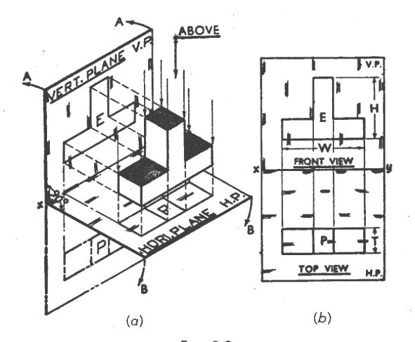
A 3D isometric view and corresponding orthographic projections (front (Source: 697c72e40165f702)
- Image Formation: Each view is a true orthographic projection, showing the object’s features without distortion.
- Usage in Automotive Engineering: This method is useful when detailing components that require a specific orientation for assembly or inspection in workshops.
Step-by-Step Procedure for Drawing First Angle Projection
- Identify the Views Required: Determine front, top, and side views essential for the component.
- Draw the Front View: Sketch the front view to scale using standard line types as per BS 8888 or ISO 128.
- Project the Top View Below the Front View: Using construction lines, project points from the front view vertically downward to locate the top view.
- Project the Right Side View to the Left of the Front View: Project horizontal lines from the front view to the left to position the right side view.
- Complete Details in Each View: Add all visible edges, hidden lines (dashed), and center lines using correct line conventions.
- Check Alignment and Scale: Ensure that all views are correctly aligned and drawn to the same scale to maintain dimensional accuracy.
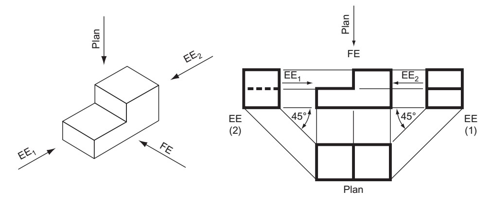
An isometric view and its corresponding orthographic projections (fron (Source: PLUMB 5 LEARNING GUIDE-1 (1))
Standards and Conventions for First Angle Projection
- Line Types: Solid thick lines for visible edges, dashed lines for hidden edges, and thin lines for dimensioning.
- Scale: Common scales include 1:1, 1:2, 1:5 depending on component size.
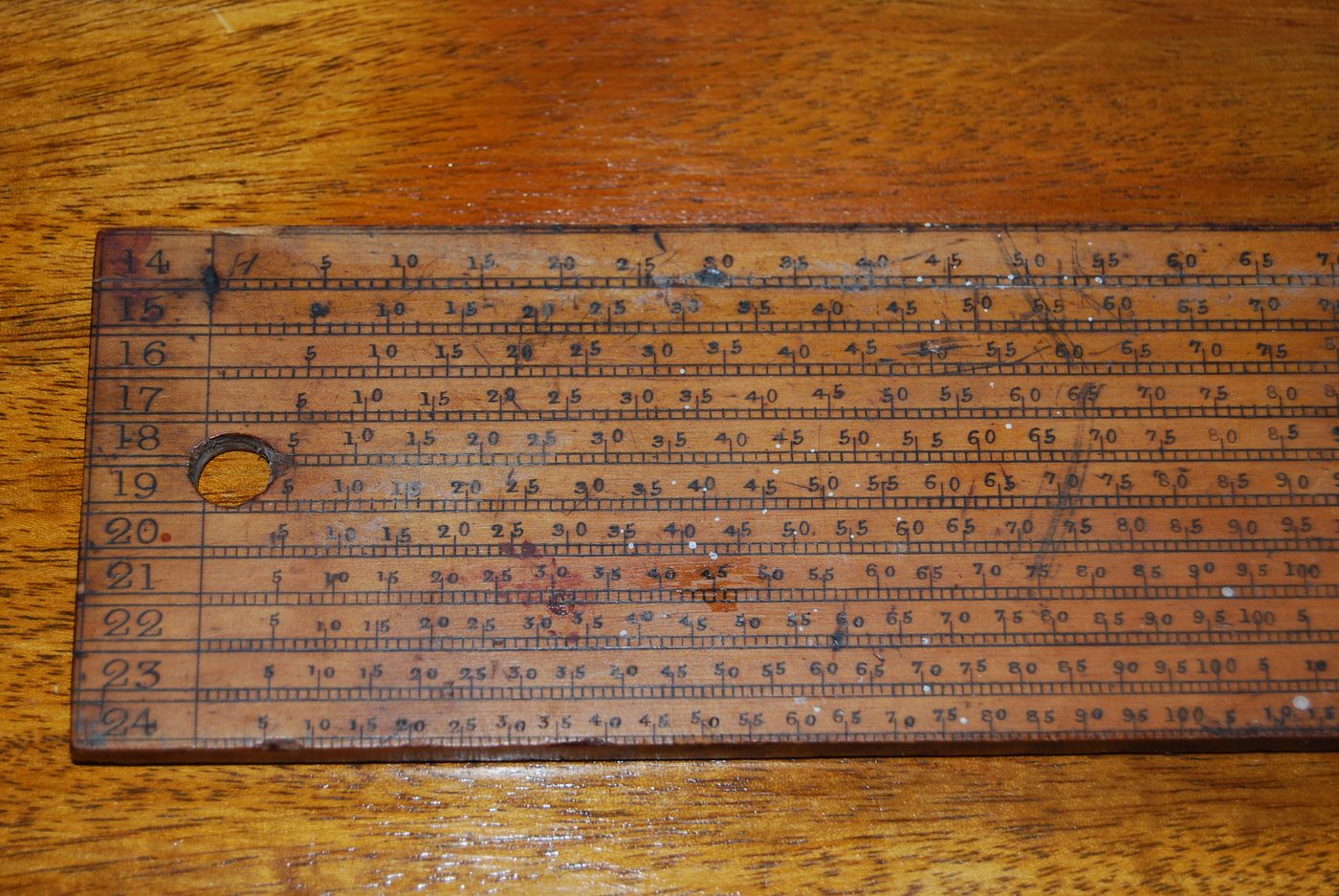
Wooden architect's scale ruler with measurement markings (Source: Wikipedia (Scale ruler))
- Title Block: Must include component name-scale, drawing number, and projection symbol (a truncated cone symbol indicating first angle).
- Projection Symbol Placement: Positioned in the title block or near the drawing border for clarity.
- Paper Size: Use standard sizes such as A3 or A4 as per ISO 5457 depending on component complexity.
Application Examples in Automotive Engineering
- Engine Component Drawings: First angle projection is used to detail cylinder head components, enabling clear visualization of ports and bolt patterns.
- Brake System Parts: Orthographic views help illustrate caliper shapes and piston arrangements for maintenance manuals.
- Transmission Gears: Gear profiles and shaft interfaces are clearly represented for manufacturing.
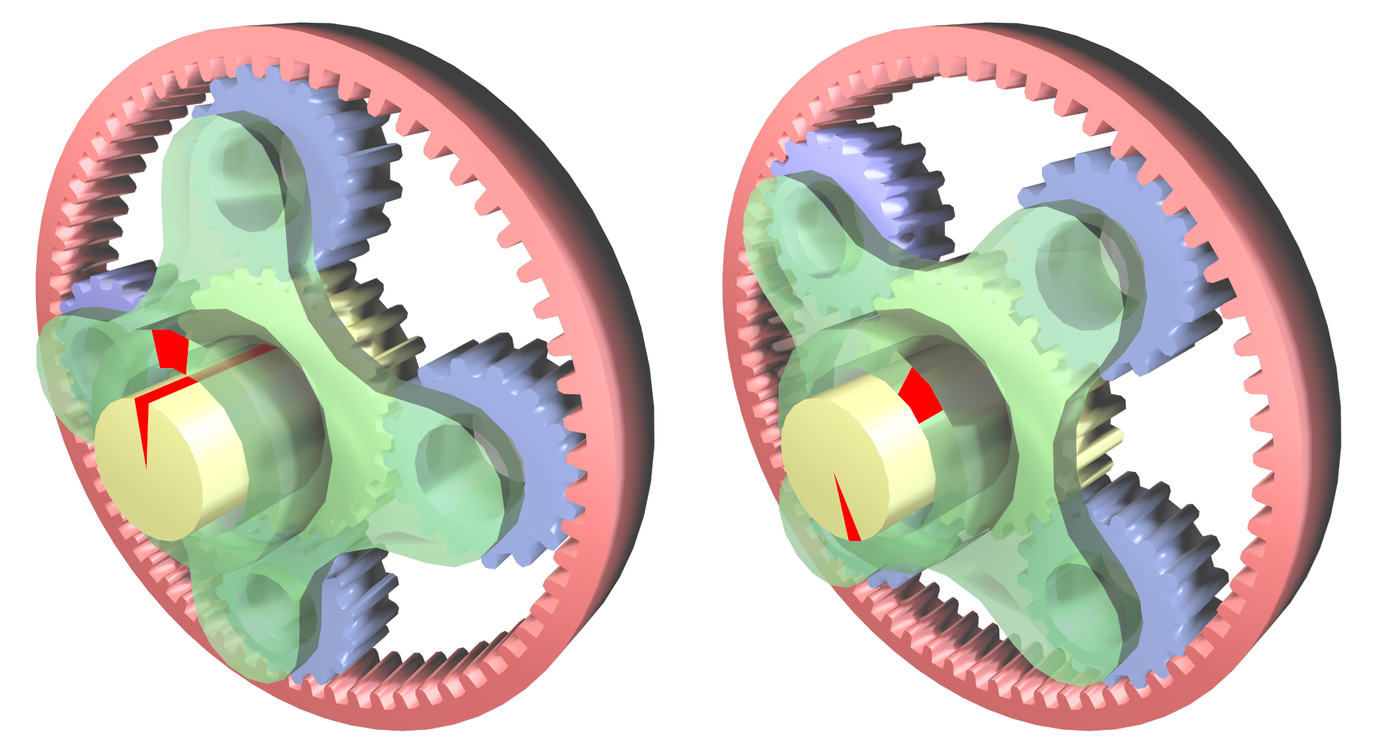
planetary transmission gear mechanism (Source: Wikimedia Commons)
- Chassis Components: Suspension arm drawings utilize first angle to show mounting points and cross-sections.
- Electrical Connectors: Housing and pin layouts are depicted to assist in assembly.
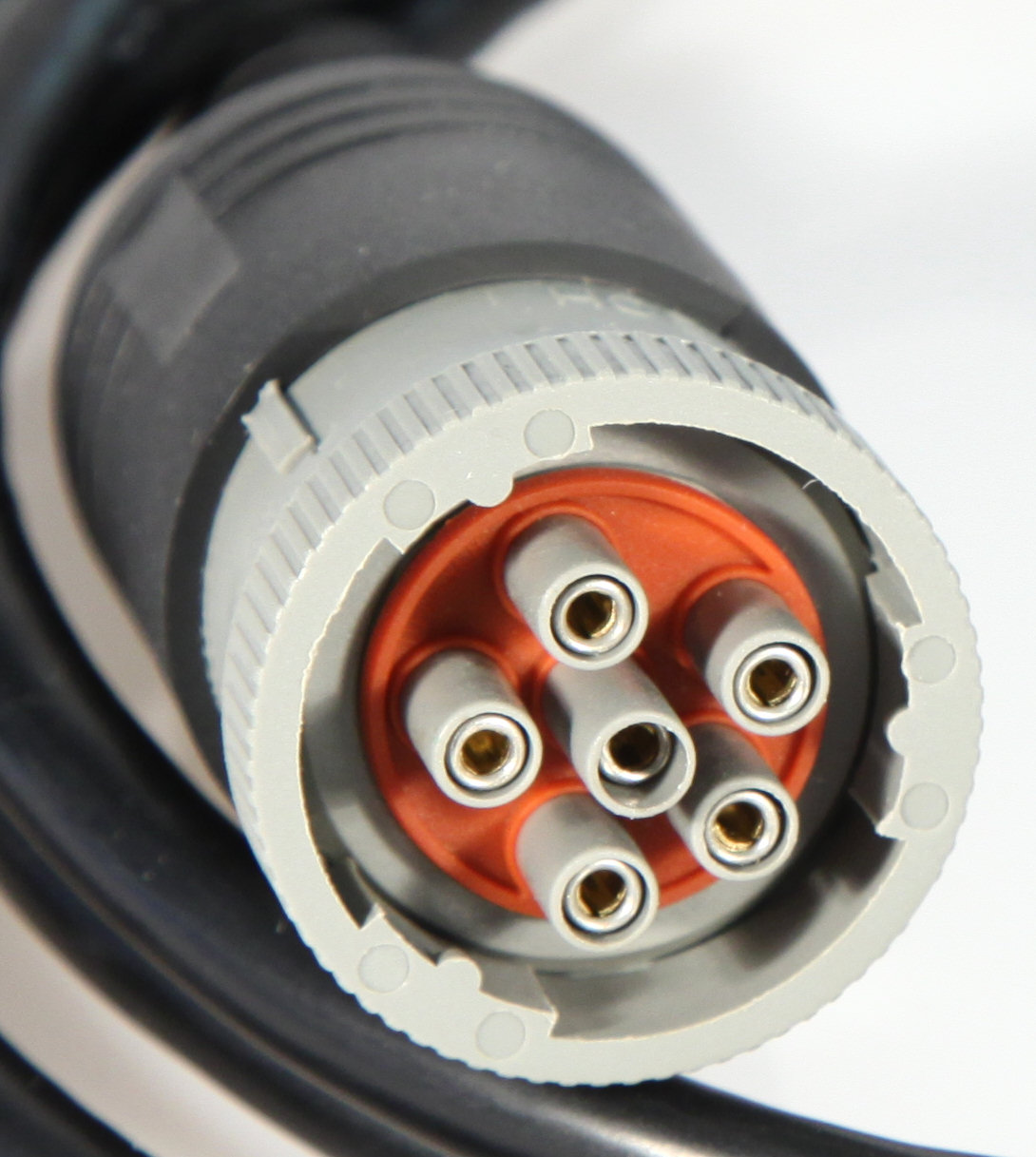
circular electrical connector with multiple pins (Source: Wikimedia Commons)
3.1.2 Third Angle Projection
Third angle projection is the preferred orthographic method in many automotive engineering environments in Kenya, especially in manufacturing and export-oriented workshops. It places the plane of projection between the observer and the object, affecting the layout of views.
Concept of Third Angle Projection
- Object Positioning: The object is located in the third quadrant, with the plane of projection between the observer and the object.
- View Arrangement: The top view is placed above the front view, and the right side view appears on the right side of the front view.
- Projection Planes: Similar to first angle but with different spatial relationships yielding a distinct layout.
- Image Formation: Maintains true scale and shape representation without distortion.
- Automotive Relevance: Common in Kenyan automotive manufacturing plants due to global alignment with ISO and BS standards.
Step-by-Step Procedure for Drawing Third Angle Projection
- Determine Necessary Views: Identify front, top, and side views based on component complexity.
- Draw the Front View: Begin by sketching the front view accurately to scale.
- Project the Top View Above the Front View: Project vertical construction lines upwards to locate the top view.
- Project the Right Side View to the Right of the Front View: Extend horizontal construction lines to the right side for the side view.
- Detail Each View: Include visible edges, hidden lines, and center lines using appropriate line styles.
- Verify Alignment and Scale Consistency: Confirm all views are aligned and uniformly scaled.
Standards and Conventions for Third Angle Projection
- Line Types: Use thick continuous lines for visible edges, dashed lines for hidden details, and thin continuous lines for dimensions.
- Scale: Select scale based on component size and drawing sheet; typical scales are 1:1, 1:2, 1:10.
- Title Block Requirements: Must include drawing title-scale, date, and the third angle projection symbol (a truncated cone symbol with the larger end on the left).
- Projection Symbol Placement: Clearly shown in the title block or drawing border.
- Paper Size and Orientation: Follow ISO 5457 recommendations for A3 or A4 sheets with landscape or portrait orientation as appropriate.
Application Examples in Automotive Engineering
- Fuel Injection Components: Detailed views of nozzles and valves for manufacturing precision.
- Exhaust System Parts: Multiple views illustrate bends and flange details.
- Steering Mechanism Components: Orthographic projections show shaft profiles and mounting brackets.
- Cooling System Parts: Radiator and pump housing drawings aid assembly and repair.
- Electrical System Housings: Battery terminal covers and fuse boxes detailed for production.
Practice Questions
- Explain the key differences between first angle and third angle projection with reference to view placement. (10 marks)
- Construct a first angle projection drawing of a simple automotive bracket with the following dimensions: length 80 mm, width 40 mm, height 30 mm. Include front, top, and right side views. (20 marks)
- Identify the correct placement of the projection symbol for third angle projection on a drawing sheet and explain its importance. (5 marks)
- Describe six steps to draw the top view in third angle projection for an automotive component. (10 marks)
The rest of this chapter
🔒Create a free account to open more of this chapter.
Free: practical guides, quick cards, workplace scenarios and more.
Create a free account 🔒3.2 Dimensioning
Dimensioning is critical in automotive technical drawings as it provides exact measurements required for manufacturing and quality control. Accurate dimensioning eliminates ambiguity, ensuring parts fit correctly and function as intended. In Kenya’s automotive…
🔒3.3 Sectional views
In automotive engineering, sectional views are crucial for revealing the internal features of components that are otherwise hidden in orthographic projections. These views enable engineers and technicians in Kenya to understand the interior construction of par…
🔒3.4 Free hand sketches
Free hand sketches are an essential skill for automotive engineering technicians in Kenya, enabling quick and effective communication of ideas and designs without reliance on CAD tools. Sketching supports conceptualization, troubleshooting, and documentation d…
Chapter Summary
This chapter focused on producing orthographic drawings of components, beginning with an exploration of orthographic projection methods, specifically first angle and third angle projections, which are fundamental for representing three-dimensional objects in two dimensions. It emphasized the importance of accurate dimensioning to convey the exact size and specifications of components clearly. The chapter also covered sectional views, which reveal internal features by cutting through objects to improve understanding of complex parts. Additionally-free hand sketches were discussed as an essential skill for quick and effective communication of ideas, with attention given to geometric forms and the proper use of drawing tools and equipment. The final section highlighted sketching mechanical components free hand, ensuring clarity and precision even in informal settings. Overall, the chapter integrated theory with practical drawing techniques to build a strong foundation in technical drawing for component production.
Self-Assessment
🔒 PDFDownload this self-assessment, with answers
A. Written Assessment
- Which projection method places the object between the observer and the plane of projection, commonly used in European automotive drawings? (2 marks)
- Identify the correct sequence of views in first angle projection for an automotive brake drum. (3 marks)
🔒20 more in this section.
Chapter Examination Questions
🔒 PDFDownload these examination questions, with worked answers
SECTION A (40 Marks) - Answer ALL Questions
- Explain the difference between first angle and third angle projection methods used in automotive component drawings. (4 marks)
- Identify the standard line types used to represent visible edges and hidden edges in orthographic drawings according to BS EN ISO 128. (4 marks)
🔒28 more in this section.
Chapter Practical Activities
Practical 1: Orthographic Drawing of a Rectangular Component Using First Angle Projection
Automotive Engineering Technology · Level 5
Technical Drawing
PRACTICAL ASSESSMENT
TIME: 4 HOURS
⬇ PDFCandidate Instructions (Candidate Tool)
Type: Individual
INSTRUCTIONS TO CANDIDATE:
1. You are required to perform the following task:
i. Create a complete orthographic drawing using first angle projection of a rectangular component 120mm length x 80mm width x 40mm height with proper dimensioning as per the provided working drawing.
2. You have been provided with the following resources for the practical task:
| Tools & Equipment | Materials |
|---|
| T-square | A2 Drawing paper |
| Engineering set | |
| Set squares | |
| Assorted pencils: 2H, 4H and HB | |
| Eraser and Masking tape | |
⬇ PDFResources Required (Cutting List)
| S/N | Item | Quantity |
|---|
| 1 | A2 Drawing paper | 1 Pc per Candidate |
| 2 | T-square | 1 Pc per Candidate |
| 3 | Engineering set | 1 Pc per Candidate |
| 4 | Set squares | 1 Pair per Candidate |
| 5 | Assorted pencils: 2H, 4H and HB | 1 Pc each per Candidate |
| 6 | Eraser and Masking tape | 1 Pc per Candidate |
| 7 | Rewritable CD | 1 Pc per Candidate |
| 8 | Computer installed with AutoCAD | 1 Pc per Candidate |
| 9 | Printing Papers | Sufficient per Candidate |
| 10 | Drawing Tables | 1 Pc per Candidate |
| 11 | Printer | 1 Pc per 5 Candidates |
⬇ PDFAssessor Guide
| Items to be Evaluated | Marks Available | Marks Obtained | Comments |
|---|
| TASK 1: Preparation and Drawing Setup |
Candidate wears appropriate PPE before starting
(Award 1 mark for correct PPE worn, zero if none) | 1 | | |
Candidate selects correct drawing tools and arranges workspace
(Award 1 mark for organized workspace and correct tools, zero if disorganized) | 1 | | |
Candidate correctly sets out drawing borders and title block
(Award 2 marks for accurate borders and title block, zero if missing or incorrect) | 2 | | |
| Sub-Total | 4 | | |
| TASK 2: Drawing Execution |
Candidate correctly draws front, top and side views in first angle projection
(Award up to 6 marks for accuracy of projection and arrangement, zero if incorrect) | 6 | | |
Candidate uses correct line types and weights as per standards
(Award 3 marks for correct use of visible, hidden and construction lines, zero if incorrect) | 3 | | |
Candidate applies proper dimensioning with correct units and placement
(Award 4 marks for complete and clear dimensioning, zero if missing or incorrect) | 4 | | |
| Sub-Total | 13 | | |
| PRODUCT CHECKLIST |
Orthographic drawing shows all three views with dimensions 120mm length, 80mm width, and 40mm height
(Award 5 marks for exact measurements matching specifications, zero if incorrect) | 5 | | |
Drawing follows first angle projection conventions correctly
(Award 4 marks for correct projection placement, zero if wrong projection method used) | 4 | | |
Drawing is neat, lines are sharp and clean, and annotations are legible
(Award 3 marks for overall neatness and clarity, zero if messy or illegible) | 3 | | |
| Sub-Total | 12 | | |
| GRAND TOTAL | 29 | | |
ASSESSMENT OUTCOME: ☐ Competent ☐ Not Yet Competent (competent if at least 50%)
Practical 2: Orthographic Drawing of a Machine Component Using Third Angle Projection
Automotive Engineering Technology · Level 5
Technical Drawing
PRACTICAL ASSESSMENT
TIME: 4 HOURS
⬇ PDFCandidate Instructions (Candidate Tool)
Type: Individual
INSTRUCTIONS TO CANDIDATE:
1. You are required to perform the following task:
i. Produce a complete orthographic drawing of a rectangular machine component 120mm length x 60mm width x 40mm height using third angle projection with accurate dimensions.
2. You have been provided with the following resources for the practical task:
| Tools & Equipment | Materials |
|---|
| T-square | A2 Drawing paper |
| Set squares | Printing Papers |
| Engineering set | Rewritable CD |
| Assorted pencils: 2H, 4H and HB | |
| Eraser and Masking tape | |
| Computer installed with AutoCAD | |
⬇ PDFResources Required (Cutting List)
| S/N | Item | Quantity |
|---|
| 1 | A2 Drawing paper | 1 Pc per Candidate |
| 2 | T-square | 1 Pc per Candidate |
| 3 | Set squares | 1 Pair per Candidate |
| 4 | Engineering set (compass, divider, protractor) | 1 Set per Candidate |
| 5 | Assorted pencils: 2H, 4H and HB | 1 Pc each per Candidate |
| 6 | Eraser and Masking tape | 1 Pc per Candidate |
| 7 | Rewritable CD | 1 Pc per Candidate |
| 8 | Computer installed with AutoCAD | 1 Pc per Candidate |
| 9 | Printing Papers | Sufficient |
| 10 | Drawing Tables | 1 Pc per Candidate |
| 11 | Printer | Shared |
⬇ PDFAssessor Guide
| Items to be Evaluated | Marks Available | Marks Obtained | Comments |
|---|
| TASK 1: Preparation and Layout |
Candidate uses appropriate PPE before starting work
(Award 2 marks for correct PPE use, zero if none) | 2 | | |
Candidate sets out drawing sheet correctly using T-square and set squares
(Award 3 marks for correct sheet layout and borders) | 3 | | |
Candidate accurately draws construction lines for third angle projection
(Award 4 marks for correct projection layout) | 4 | | |
Candidate uses engineering set for arcs and circles accurately
(Award 2 marks for correct use of compass and divider) | 2 | | |
| Sub-Total | 11 | | |
| TASK 2: Drawing and Dimensioning |
Candidate draws front, top and side views correctly in third angle projection
(Award 6 marks for correct views placement and shape) | 6 | | |
Candidate applies accurate dimensioning to length (120mm), width (60mm), and height (40mm)
(Award 5 marks for correct and clear dimensioning) | 5 | | |
Candidate uses correct line types and thicknesses for outlines and hidden details
(Award 3 marks for line quality and types) | 3 | | |
Candidate includes title block and scale on the drawing
(Award 2 marks for inclusion and accuracy of title block) | 2 | | |
| Sub-Total | 16 | | |
| PRODUCT CHECKLIST |
Orthographic drawing shows correct third angle projection with front, top and side views
(Award 6 marks for overall correctness of projection) | 6 | | |
All principal dimensions (120mm length, 60mm width, 40mm height) are accurate within ±1mm
(Award 6 marks for dimensional accuracy) | 6 | | |
Drawing is neat, clean, and free from smudges or erasures
(Award 4 marks for presentation quality) | 4 | | |
Title block, scale, and projection symbol are correctly placed and labeled
(Award 3 marks for correct annotation) | 3 | | |
| Sub-Total | 19 | | |
| GRAND TOTAL | 46 | | |
ASSESSMENT OUTCOME: ☐ Competent ☐ Not Yet Competent (competent if at least 50%)
🔒Draw sectional views of a mechanical flange couplingPractical 3
🔒Free Hand Sketching of Geometric FormsPractical 4
🔒Free hand orthographic sketches of a stepped shaftPractical 5
🔒Produce Accurate Orthographic Layouts Using Drawing ToolsPractical 6
🔒Dimension orthographic drawing of a mechanical componentPractical 7
🔒Produce orthographic assembly drawing of a mechanical couplingPractical 8
🔒Draw Sectional Views of a Cylindrical Valve Housing Using First and Third Angle ProjectionsPractical 9
🔒Free hand sketches of technical drawing tools and equipmentPractical 10
