
By the end of this chapter, you will be able to:
Mastering these skills ensures you can work safely and effectively with electrical systems, protecting both people and equipment in the real trade.
Protection principles are essential in any electrical installation to detect faults promptly and isolate the affected sections, preventing damage and hazards. In Kenyan institutions such as county referral hospitals or financial institutions, reliable protection systems minimize downtime and enhance safety, supporting critical services and data integrity. This section covers the concepts of protection zones and protection systems, foundational for understanding how to safeguard electrical networks.
Protection zones define specific areas within an electrical system where protective devices monitor and isolate faults to prevent system-wide failures. Dividing an installation into zones allows targeted responses to faults, improving system reliability and safety.
Protection zones are designated sections of an electrical network, typically bounded by protective devices such as circuit breakers and relays. Their purpose is to confine faults within limited areas, avoiding unnecessary disconnection of healthy parts of the system, which is critical in environments like universities where uninterrupted power supply to laboratories is essential.
Properly defined protection zones enhance system reliability by reducing the risk of widespread outages. For example, in a county government office, a fault confined to a feeder zone supplying lighting will not affect power to the data center, maintaining essential operations.
Challenges include accurately assessing fault levels, especially in expanding installations like growing agricultural cooperatives, and ensuring coordination among multiple protective devices to avoid overlap or gaps in protection.
Protection systems consist of devices and schemes designed to detect abnormal conditions and isolate faulty parts promptly. Their correct application is vital for preventing equipment damage, ensuring personnel safety, and maintaining service continuity.
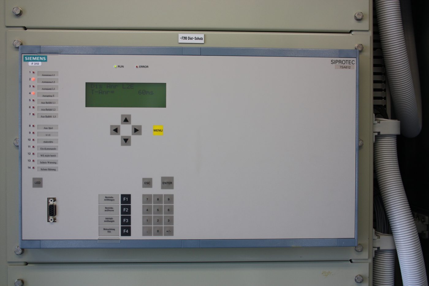
Siemens SIPROTEC protective relay panel (Source: Wikimedia Commons)
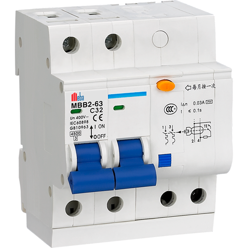
Three-pole circuit breaker with switches (Source: Wikimedia Commons)
Three types of electrical protective devices (Source: BUILDING SERVICES & PROTECTION-NOTES-7-61-1)
Protection systems must operate selectively, isolating only the faulty section without affecting other parts. Coordination involves setting device parameters so that the device closest to the fault acts first. For example, in a university, coordination prevents unnecessary power cuts to lecture halls when a fault occurs in a laboratory circuit.
Effective protection systems prevent electrical fires, equipment damage, and personnel injuries. For instance, in a hotel, earth fault protection reduces risk of electric shock to guests and staff.
Challenges include ensuring compatibility of devices from different manufacturers, adapting to system expansions in growing SACCOs, and maintaining protection settings amid changing load profiles.
Create a free account to open more of this chapter.
Free: practical guides, quick cards, workplace scenarios and more.
Create a free accountThis chapter explored the fundamental principles behind system and equipment protection, emphasizing the importance of defining protection zones and selecting appropriate protection systems to safeguard electrical installations. It detailed the process of designing protection systems, including the preparation of accurate protection system drawings, the correct sizing of protective devices, and the strategic placement of these systems within electrical networks. Various earthing system designs were examined, covering TT, TNC, TNCS, IT, and TNS configurations, each with distinct characteristics and applications to ensure safety and reliability. The chapter also covered essential testing methods for earthing systems, focusing on earth resistance and earth loop impedance tests to verify system effectiveness. Different types of lightning strikes were identified, highlighting their impact on electrical infrastructure. Finally, the design of lightning protection systems was addressed, including the use of lightning arrestors, the development of lightning protection drawings, and considerations for sizing these systems to protect buildings and equipment from lightning damage.
Type: Individual
| Tools & Equipment | Materials |
|---|---|
| Multimeter | 1.5 mm2 PVC sheathed cable |
| Spirit level | 2.5 mm2 PVC sheathed cable |
| Assorted spanners and screwdrivers | 4-way consumer control unit |
| PPEs (Boots, dustcoat/overall, safety boots, gloves, goggles) | 6A/10A MCB circuit breaker |
| 32A Double Pole Circuit Breaker | |
| Surge arrester | |
| Ball spike | |
| 3-phase energy meter | |
| Junction box | |
| Deep pattress box | |
| Shallow pattress box | |
| 1 gang two way switch | |
| 1 gang one way switch | |
| 13A socket outlet | |
| Fluorescent lamp complete | |
| Straight bulb holder | |
| Incandescent bulb | |
| Wood screws 9" | |
| Cable clips 12mm |
| S/N | Item | Quantity |
|---|---|---|
| 1 | 1.5 mm2 PVC sheathed cable | 5 metres per Candidate |
| 2 | 2.5 mm2 PVC sheathed cable | 5 metres per Candidate |
| 3 | 4-way consumer control unit | 1 Pc per Candidate |
| 4 | 6A/10A MCB circuit breaker | 2 Pcs per Candidate |
| 5 | 32A Double Pole Circuit Breaker | 1 Pc per Candidate |
| 6 | Surge arrester | 1 Pc per Candidate |
| 7 | Ball spike | 1 Pc per Candidate |
| 8 | 3-phase energy meter | 1 Pc per Candidate |
| 9 | Junction box | 1 Pc per Candidate |
| 10 | Deep pattress box | 1 Pc per Candidate |
| 11 | Shallow pattress box | 2 Pcs per Candidate |
| 12 | 1 gang two way switch | 1 Pc per Candidate |
| 13 | 1 gang one way switch | 1 Pc per Candidate |
| 14 | 13A socket outlet | 1 Pc per Candidate |
| 15 | Fluorescent lamp complete | 1 Pc per Candidate |
| 16 | Straight bulb holder | 1 Pc per Candidate |
| 17 | Incandescent bulb | 1 Pc per Candidate |
| 18 | Wood screws 9" | 10 Pcs per Candidate |
| 19 | Multimeter | 1 Pc per Candidate |
| 20 | 240V AC power supply | Reliable per Candidate |
| 21 | Spirit level | 1 Pc per Candidate |
| 22 | PPEs (Boots, dustcoat/overall, safety boots, gloves, goggles) | 1 set per Candidate |
| 23 | Assorted spanners and screwdrivers | 1 set per Candidate |
| 24 | Cable clips 12mm | 1 packet per Candidate |
| Items to be Evaluated | Marks Available | Marks Obtained | Comments |
|---|---|---|---|
| TASK 1: Preparation and Safety | |||
| Wore personal protective equipment (boots, gloves, goggles, dustcoat) (Award 2 or 0) | 2 | ||
| Ensured clean and safe working area before starting (Award 1 or 0) | 1 | ||
| Listed and prepared all tools and materials (Award 2 or 0) | 2 | ||
| Sub-Total | 5 | ||
| TASK 2: Circuit Diagram and Layout | |||
| Drew correct and neat single phase protection circuit schematic (Award up to 10 marks for accuracy and completeness) | 10 | ||
| Observed correct colour coding for wiring (Award 2 or 0) | 2 | ||
| Marked layout positions of components on installation board (Award 3 or 0) | 3 | ||
| Sub-Total | 15 | ||
| TASK 3: Installation and Wiring | |||
| Fixed consumer control unit, MCBs, surge arrester, energy meter and switches firmly and level (Award 5 or 0) | 5 | ||
| Installed cables with correct sizes and neat routing (Award 4 or 0) | 4 | ||
| Used cable clips spaced evenly and firmly fixed (Award 2 or 0) | 2 | ||
| Made correct cable terminations without damage to conductors (Award 4 or 0) | 4 | ||
| Sub-Total | 15 | ||
| TASK 4: Termination of Protective Devices | |||
| Terminated surge arrester correctly (Award 2 or 0) | 2 | ||
| Terminated ball spike correctly (Award 2 or 0) | 2 | ||
| Terminated energy meter correctly (Award 2 or 0) | 2 | ||
| Terminated MCBs correctly (Award 2 or 0) | 2 | ||
| Sub-Total | 8 | ||
| TASK 5: Testing and Commissioning | |||
| Performed continuity test on wiring (Award 3 or 0) | 3 | ||
| Performed insulation resistance test (Award 3 or 0) | 3 | ||
| Performed polarity test (Award 3 or 0) | 3 | ||
| Demonstrated correct circuit operation including protection devices (Award 5 or 0) | 5 | ||
| Applied good housekeeping after completion (Award 2 or 0) | 2 | ||
| Sub-Total | 16 | ||
| PRODUCT CHECKLIST | |||
| Circuit wiring and component installation correspond to schematic and layout (neatness, proper spacing, level fixing) (Award up to 10 marks for accuracy and neatness) | 10 | ||
| Circuit measurements match specified dimensions: installation board 1000mm x 1000mm (Award 5 or 0) | 5 | ||
| Correct colour coding and labelling of all conductors and devices (Award 5 or 0) | 5 | ||
| Sub-Total | 20 | ||
| GRAND TOTAL | 79 | ||
Type: Individual
| Tools & Equipment | Materials |
|---|---|
| Permanent marker pen black | Electrical system layout drawing A2 size |
| Permanent marker pen red | Labels/tags |
| Ruler 300 mm | |
| Protractor 180° | |
| Colored adhesive tape (red, yellow, green) |
| S/N | Item | Quantity |
|---|---|---|
| 1 | Electrical system layout drawing A2 size | 1 sheet per Candidate |
| 2 | Permanent marker pen black | 1 Pc per Candidate |
| 3 | Permanent marker pen red | 1 Pc per Candidate |
| 4 | Ruler 300 mm | 1 Pc per Candidate |
| 5 | Protractor 180° | 1 Pc per Candidate |
| 6 | Colored adhesive tape (red, yellow, green) | 1 roll each per Candidate |
| 7 | Labels/tags | 10 pcs per Candidate |
| 8 | PPE (Safety boots, gloves, goggles) | 1 set per Candidate |
| Items to be Evaluated | Marks Available | Marks Obtained | Comments |
|---|---|---|---|
| TASK 1: Preparation and Safety | |||
| Wore personal protective equipment including safety boots, gloves, and goggles (Award 2 marks for full PPE use or 0) | 2 | ||
| Acquired and assembled all necessary tools and materials (Award 2 marks for complete set or 0) | 2 | ||
| Sub-Total | 4 | ||
| TASK 2: Identification and Marking of Protection Zones | |||
| Correctly identified main protection zones on the electrical system layout (Award 2 marks each for correctly identifying 3 main zones or 0) | 6 | ||
| Marked protection zones clearly using colored adhesive tape according to standard colour code (Award 2 marks each for correct use of 3 colors or 0) | 6 | ||
| Used permanent markers to label protection zones accurately (Award 4 marks for clear and accurate labelling or 0) | 4 | ||
| Applied ruler and protractor correctly for precise marking and angles (Award 4 marks for neat and accurate markings or 0) | 4 | ||
| Sub-Total | 20 | ||
| TASK 3: Documentation and Housekeeping | |||
| Placed labels/tags correctly on each protection zone (Award 4 marks for correct placement and legibility or 0) | 4 | ||
| Ensured work area was clean and tools were properly stored after completion (Award 2 marks for good housekeeping or 0) | 2 | ||
| Sub-Total | 6 | ||
| PRODUCT CHECKLIST | |||
| Protection zones marked on the layout with correct dimensions: 600 mm x 450 mm (Award 5 marks for exact dimensions or 0) | 5 | ||
| Protection zones clearly differentiated by colour and labelled as per standards (Award 5 marks for clear differentiation and correct labelling or 0) | 5 | ||
| Markings are neat, straight, and within the layout boundaries (Award 4 marks for neatness and accuracy or 0) | 4 | ||
| Sub-Total | 14 | ||
| GRAND TOTAL | 44 | ||
At the start of this chapter we promised you would be able to:
Tick each one you can genuinely do.
So, are you there yet?
You're competent when you can confidently do 50% or more of what this chapter promised.
Sign in to record how you're doing.