Performing metal testing is fundamental to welding professionals who must ensure the integrity, quality, and safety of welded structures in Kenya’s diverse industries. Accurate metal testing helps detect defects, verify material properties, and confirm compliance with engineering standards. This chapter introduces the essential machines, tools, and equipment used in metal inspection and testing, emphasizing their correct use and maintenance to deliver reliable results in environments ranging from county government fabrication workshops to industrial manufacturing plants.
6.1 Metal inspection machines, tools and equipment
Metal testing requires specialized instruments and equipment to evaluate mechanical properties, surface conditions, and internal integrity of metals. Welding professionals need a clear understanding of available tools and machines, their applications, and upkeep to prevent errors that could compromise weld quality and safety.
6.1.1 Tools
Inspection tools are the hand-held and portable items used to prepare a weld for examination, measure it, and detect surface defects. They are cheap compared with laboratory machines, yet most weld rejections start with a measurement or a surface check made with one of them. A fabricator building roof trusses for a boarding school dining hall, for example, uses an air-driven chipping hammer to expose the weld, a gauge to measure it, and a yoke to check it for cracks.
The table below lists the common metal inspection tools.
| Name |
Specification |
Use |
| Pneumatic Chipping Hammer |
Air-driven, working pressure as stated on the tool plate (commonly about 6 bar) |
Removes slag from weld beads before inspection |
| Needle Scaler |
Bundle of hardened steel needles driven by compressed air |
Cleans scale, rust and spatter from irregular surfaces |
| Vernier Caliper |
Measurement range 0-150 mm |
Measures external and internal dimensions |
| Micrometer |
Measurement range 0-25 mm, accuracy 0.01 mm |
Measures thickness and diameter with precision |
| Weld Gauge Set |
Graduated steel fillet and bridge cam gauges |
Measures leg length, throat, reinforcement height and undercut depth |
| Surface Roughness Comparator |
Set of standard roughness plates |
Evaluates surface finish quality visually |
| Portable Hardness Tester |
Measures Rockwell and Brinell scales |
Assesses metal hardness on-site |
| Magnetic Particle Yoke |
Operating voltage 110V/220V, magnetising force verified by a lift test |
Detects surface and near-surface cracks in ferromagnetic metals |
6.1.1.1 Pneumatic tools
Pneumatic tools are driven by compressed air instead of electricity, which makes them light, powerful and safe to use in damp or confined places. In inspection work they prepare the weld so that defects are not hidden by slag, scale or spatter. Example: a contractor erecting a steel footbridge uses a chipping hammer and needle scaler to clean every weld before the inspector arrives.
- Chipping hammer: A piston strikes a chisel or pointed bit at high frequency to break slag off weld beads. The bit must be sharp and rounded at the corners so that it does not gouge the parent metal.
- Needle scaler: Many thin hardened needles vibrate against the surface and remove rust, scale and spatter. It cleans uneven surfaces such as fillet welds better than a flat chisel.
- Pneumatic grinder and wire brush: Air-driven rotary tools remove spatter and light surface contamination and leave a clean, bright surface for visual or magnetic particle examination. Full weld preparation is covered later in this chapter.
- Air compressor: It supplies the air. Its delivery pressure and flow must match the tool, because an undersized compressor makes the tool lose power and strike weakly.
- Filter, regulator and lubricator unit: This removes water and dirt from the air, sets the working pressure and adds a fine mist of oil to protect internal parts. It is fitted close to the tool.
- Hoses and couplings: Rated hoses with secure couplings carry the air. A damaged hose can whip violently when pressurised, so it must be replaced, never taped.
6.1.1.2 Gauges
Gauges are measuring and comparing instruments that turn a visual impression into a number that can be checked against a drawing or acceptance limit. Using them removes guesswork when judging weld size, fit-up and surface condition. Example: an inspector at a hotel's steel staircase project measures each fillet weld leg with a gauge instead of judging it by eye.
- Vernier calipers allow welders to measure weld bead width, depth of undercut, and gaps between components with precision critical for fit-up and quality control.
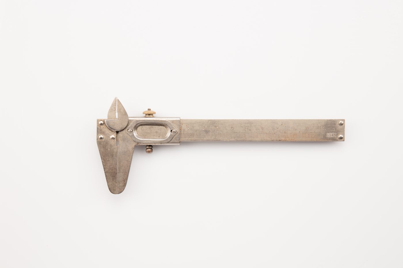
A vernier caliper on white background (Source: Wikimedia Commons)
- Micrometers provide highly accurate thickness measurements for base metals and weld deposits, ensuring materials meet design specifications. On a metric micrometer the sleeve shows whole and half millimetres and the thimble shows hundredths of a millimetre.
- Weld gauges include fillet gauges, which check leg length and throat of fillet welds, and bridge cam gauges, which check reinforcement height, undercut depth and misalignment. Each has a set of calibrated profiles or a sliding scale that is read directly against the weld.
- Surface roughness comparators enable welders and inspectors to visually match surface textures to standards, ensuring welds are free from excessive spatter and irregularities that can cause fatigue failures.
- Portable hardness testers help verify the hardness of heat-affected zones (HAZ) post-welding, which affects weld toughness and brittleness.
Example: reading a micrometer.
Reading = sleeve reading + thimble reading
Sleeve reading = 12.5 mm
Thimble reading = 34 divisions × 0.01 mm = 0.34 mm
Reading = 12.5 + 0.34 = 12.84 mm
6.1.1.3 Electromagnets
An electromagnet produces a magnetic field only while current flows through its coil, so the field can be switched on and off at will. In weld inspection this is used to magnetise steel so that surface cracks attract and show up with magnetic particles. Example: a county water department checking welds on a steel tank tower uses a portable electromagnet to examine the shell seams.
- Magnetic particle yoke: A coil wound on a U-shaped iron core with articulated legs. When the legs are placed on the weld, magnetic flux passes through the steel between them and defects across the field show up. Yokes are essential in non-destructive testing (NDT) for detecting cracks and inclusions on weld surfaces, especially in structural steel used in county government infrastructure projects.
- Alternating current (AC) yoke: It runs from the mains supply and is good for surface-breaking defects. Its changing field also makes the particles move, which helps them gather at flaws.
- Direct current (DC) yoke: It penetrates deeper than an AC yoke, so it can find near-surface defects, but it gives less particle movement.
- Permanent magnet yoke: It needs no power supply, which is useful on remote sites where no power is available, but its field is weaker than that of an electromagnetic yoke.
- Magnetic holders and clamps: Switchable electromagnetic or permanent-magnet squares hold plates at set angles during fit-up. They free both hands and keep the joint aligned for welding and measurement.
- Lift test: The magnetising force of a yoke is checked by lifting a standard steel block at the leg spacing used. A yoke that fails the test must be repaired before use.
- Safety points: Do not energise the yoke when its legs are off the surface, as it may arc and burn the metal. Keep the legs clean, and keep pacemaker wearers away from strong magnetic fields.
6.1.2 Use and care of tools
Understanding the correct operation and upkeep of metal inspection tools ensures accurate measurements and extends equipment lifespan, essential for welding quality assurance. A tool that is dirty, worn or out of calibration gives readings that look right but are wrong, and a weld may be wrongly accepted or rejected as a result. Example: a school workshop that wipes and stores its micrometers after every lesson still has accurate instruments years later.
Correct handling techniques
- Always hold measuring tools gently but firmly to avoid bending or dropping, which can misalign scales or damage sensitive parts.
- Position calipers and micrometers perpendicular to the surface being measured to avoid skewed readings.
- For magnetic particle yokes, ensure the metal surface is clean and dry before application to maximize magnetic field penetration and defect visibility.
- When using hardness testers, select the correct indenter and load settings based on metal type and thickness to obtain valid hardness values.
- Use surface roughness comparators under good lighting conditions and compare surfaces side-by-side for accurate assessment.
- Before using a pneumatic tool, check that the air pressure does not exceed the tool rating, fit the hose securely, and wear eye and hearing protection.
- Never point a pneumatic tool at another person, and release the air supply before changing a bit or disconnecting a hose.
Preventive maintenance practices
- Cleanliness: Clean tools after each use with appropriate solvents or cloths to remove dirt, oil, and metal particles that could affect accuracy.
- Rust protection: Wipe tools with a light machine oil after use to protect metal surfaces from rust and oxidation, typical in coastal or humid workshop environments.
- Calibration: Vernier calipers and micrometers require regular calibration against gauge blocks, and other tools should be checked periodically using certified standards and adjusted or serviced as needed.
- Storage: Store tools in protective cases or designated drawers in a dry, dust-free environment, preferably with silica gel packs to reduce moisture and avoid mechanical damage and corrosion.
- Battery checks: Instruments like portable hardness testers and magnetic particle yokes may depend on batteries or a power supply; check and replace batteries regularly to avoid test interruptions.
- Pre-use inspection: Inspect tools visually for wear, rust, or damage before use to prevent faulty readings or injury.
- Replacing parts: Replace worn or damaged parts promptly; for example, replace worn micrometer anvils to maintain measurement consistency.
- Pneumatic tool care: Drain water from the compressor and air line daily, add a few drops of pneumatic tool oil to the inlet or keep the lubricator filled, and check hoses and couplings for cracks and leaks.
- Training: Train all welding staff on proper tool use and maintenance protocols to minimize human error and equipment misuse.
Troubleshooting common tool issues
- If a vernier caliper or micrometer sticks or jams, clean the sliding surfaces and apply a small amount of light lubricant.
- Inaccurate readings may indicate the need for recalibration or replacement of worn components.
- Magnetic particle yokes not generating a strong enough field may have electrical faults or worn coils requiring professional servicing.
- Hardness testers showing erratic values often have damaged indenters or require battery replacement.
- Surface roughness comparators that are worn or damaged should be replaced to maintain reliable visual assessments.
- A pneumatic tool that is weak or slow usually has low air pressure, a clogged filter, a leaking hose or a lack of lubrication, and should be checked in that order.
6.1.3 Machines
Metal testing machines offer advanced capabilities for evaluating mechanical properties such as tensile strength, impact resistance, and hardness on a laboratory or workshop scale. Some machines also examine the inside of a weld without damaging it. Example: a steel fabricator supplying a bank's new headquarters may use a tensile machine for sample coupons and an ultrasonic set for the finished welds.
The table below lists the types of metal testing machines.
| Name |
Specification |
Use |
| Universal Testing Machine (UTM) |
Capacity 100 kN to 500 kN |
Measures tensile, compression, and bending strength |
| Ultrasonic Flaw Detector |
Frequency 1-10 MHz, portable |
Detects internal defects using sound waves |
| Radiographic Equipment |
X-ray set or sealed gamma source projector with detector |
Shows internal defects as an image of density differences |
| Charpy Impact Tester |
Energy range 0-300 J |
Measures impact toughness of metals |
| Rockwell Hardness Tester |
Loads: 60 kgf, 100 kgf, 150 kgf |
Measures hardness using Rockwell scale |
| Optical Emission Spectrometer |
Wavelength range 100-700 nm |
Analyzes metal composition and alloy content |
6.1.3.1 Universal testing machine
A universal testing machine (UTM) pulls, compresses or bends a specimen at a controlled rate while it records the force and the extension. It is called universal because the same frame can carry out several types of test by changing the grips and fixtures. UTMs are employed in fabrication workshops to test weld samples for tensile strength, ensuring welds meet structural design requirements in projects like hospital steel frameworks.
- Load frame: A rigid frame with a fixed base and a moving crosshead that carries the force through the specimen.
- Drive system: Hydraulic or electromechanical, it moves the crosshead at a set speed so that the load is applied smoothly.
- Load cell: It measures the force applied. Its capacity must suit the specimen, and it is the part that is calibrated.
- Grips and fixtures: Wedge grips hold round or flat tensile specimens, while compression plates and bend rollers are fitted for other tests.
- Extensometer: It clamps on the specimen and measures small extensions accurately, which is needed to find yield behaviour.
- Controller and software: They set the test speed, display the force-extension curve and store the results.
Capacity must be checked before testing, because a specimen that needs more force than the machine can give cannot be broken.
Example: can a 100 kN machine break a 20 mm diameter round specimen of steel with tensile strength of about 450 N/mm²?
Area = π × d² ÷ 4
Area = π × 20² ÷ 4 = π × 400 ÷ 4 = 314.2 mm²
Force = tensile strength × area
Force = 450 × 314.2 = 141,390 N
Force ≈ 141 kN
The force of 141 kN is greater than 100 kN, so a machine with a higher capacity, or a specimen with a smaller diameter, is needed.
6.1.3.2 Ultrasonic testing machine
An ultrasonic testing machine, or flaw detector, sends high-frequency sound into the metal and displays the echoes that return. A crack, lack of fusion or porosity reflects the sound sooner than the back wall, so its depth and approximate size can be read from the screen. Ultrasonic flaw detectors enable non-destructive examination of welds for internal cracks or porosity that are invisible to surface inspection tools. Example: a farm equipment maker uses a portable set to check the welds on a grain silo support frame without cutting it.
- Pulser-receiver and display: The unit generates the electrical pulse and shows the returned signal, usually as a trace of echo height against time.
- Probes: Straight-beam (normal) probes send sound straight into the plate, and angle-beam probes send it into the weld at a set angle. Typical frequencies lie in the 1-10 MHz range.
- Couplant: A gel, paste or oil between the probe and the metal that removes air gaps so that the sound can enter the metal.
- Cables and connectors: They link the probe to the unit and must be undamaged, because a faulty cable gives noisy or lost signals.
- Calibration blocks: Standard steel blocks of known thickness and shape are used to set the time base and the sensitivity before testing, such as the IIW (V1) block.
- Battery and power: Portable sets run on rechargeable batteries so that they can be used on site at height or in the field.
6.1.3.3 Radiography
Radiography uses penetrating radiation to produce an image of the inside of a weld on a film or digital detector. Dense metal absorbs more radiation and voids or cracks absorb less, so defects appear as light or dark shadows. It gives a permanent record, but the radiation source requires licensed operators and strict controls. Example: a pipeline contractor radiographs welded joints of a water main before it is buried. This section covers the equipment, and the full inspection procedure belongs to the radiography inspection topic.
- X-ray set: An X-ray tube generates radiation only when it is switched on, with the voltage (kV) controlling how much metal it can penetrate. Cooling is needed because the tube heats up during use.
- Gamma projector: It holds a sealed radioactive source, such as iridium-192, inside a shielded container. The source is wound out through a guide tube to the exposure position by a remote crank, so it is never handled directly.
- Detector: Film in a light-tight cassette or a digital detector records the radiation that passes through the weld.
- Image quality indicators: Wire or hole-type penetrameters placed on the weld show whether the image is sensitive enough to reveal the smallest defect of interest.
- Radiation monitoring equipment: A calibrated survey meter measures radiation levels in the area, and each worker wears a personal dosimeter to record the dose received.
- Barriers and warning signs: Ropes, signs and lights mark the controlled area so that nobody enters during exposure.
Charpy, Rockwell and spectrometer machines
Besides the machines above, three other instruments are found in welding laboratories. They measure toughness, hardness and chemical composition, and each supports weld quality in a different way. The test methods themselves are covered in the destructive testing topics.
- Charpy Impact Testers assess the toughness of weld metals and heat-affected zones, critical for safety in cold or high-stress environments such as refrigeration plants.
- Rockwell Hardness Testers provide precise hardness data to confirm proper heat treatment and welding procedures, preventing brittle welds in pressure vessels.
- Optical Emission Spectrometers verify chemical composition of filler metals and base metals, ensuring compatibility and preventing weld failures from improper alloy use.
6.1.4 Use and care of machines
Proper operation and maintenance of metal testing machines safeguard investment, ensure accurate results, and prolong machine service life in busy welding workshops. A machine that is not calibrated or is poorly maintained may give results that look reliable but lead to wrong decisions on weld acceptance. Example: a county technical college keeps a logbook beside its UTM so that every calibration, service and fault is recorded.
Operating procedures for testing machines
- Conduct pre-test calibration using certified reference standards to verify machine accuracy before each testing cycle.
- Prepare test specimens according to standardized dimensions and surface finish to eliminate variability.
- Follow manufacturer instructions strictly, including load application rates in tensile testing and impact energy settings.
- Monitor machine controls and sensors during testing to detect anomalies or malfunctions early.
- Record test data meticulously for traceability and quality assurance documentation.
- For ultrasonic testing, set the time base and sensitivity on the calibration block with the same probe, cable and couplant that will be used on the weld.
- For radiography, set the exposure from the manufacturer's exposure chart or a trial exposure, and confirm the image quality indicator is visible on the result.
Maintenance and servicing of machines
- Schedule regular preventive maintenance including lubrication of moving parts, inspection of hydraulic systems, and replacement of worn grips or anvils in UTMs.
- Clean ultrasonic probes and replace couplant fluids periodically to maintain signal clarity.
- Inspect electrical wiring and connections in impact testers and hardness machines to prevent faults.
- Keep optical components in spectrometers clean and calibrated for accurate elemental analysis.
- Have gamma projectors, guide tubes and sealed sources inspected, leak-tested and serviced only by authorised, trained persons, and calibrate survey meters at the intervals set by the supplier or regulator.
- Train machine operators on routine maintenance tasks and troubleshooting to minimize downtime.
Safety considerations in machine use
- Ensure all safety guards and emergency stop buttons are functional and accessible during machine operation.
- Use appropriate personal protective equipment such as gloves, safety glasses, and hearing protection.
- Keep the testing area clear of unnecessary personnel to avoid injuries from moving parts or specimen failure.
- Follow lockout/tagout procedures during machine maintenance to prevent accidental startup.
- Be aware of hazards from hydraulic fluid leaks, electrical faults, and sharp specimen edges during testing and servicing.
- In radiography, reduce exposure by limiting time near the source, keeping distance from it, and using shielding. Wear a dosimeter, mark and guard the controlled area, and store gamma sources in a locked, shielded and licensed store.
Machine selection criteria
Choosing the right machine saves money and avoids unreliable results. The choice depends on what must be measured, where the work is done and how often it is repeated.
- Required test type and material properties dictate machine choice; for example, tensile testing requires a UTM, while surface crack detection needs magnetic particle or dye penetrant equipment.
- Portability considerations influence selection; on-site weld inspection often uses handheld ultrasonic flaw detectors rather than stationary lab machines.
- Accuracy and capacity must match the specimen size and expected load; large structural components require high-capacity UTMs.
- Budget constraints and frequency of testing influence whether to purchase or outsource testing services.
- Compliance with Kenya Bureau of Standards (KEBS) and international welding codes (e.g. AWS, ISO) guides machine specifications.
Practice Questions
- Explain the key differences in use and maintenance between handheld metal inspection tools and testing machines. (10 marks)
- Describe the procedure for preparing a weld specimen for tensile testing using a Universal Testing Machine. (12 marks)
- Identify five common metal inspection tools used in welding and explain their specific applications. (15 marks)
- Discuss the safety measures that must be observed when operating metal testing machines in a welding workshop. (8 marks)
- Outline the steps involved in calibrating a portable hardness tester and explain why calibration is important. (10 marks)
The rest of this chapter
🔒Create a free account to open more of this chapter.
Free: practical guides, quick cards, workplace scenarios and more.
Create a free account 🔒6.2 Consumables
In welding metal testing, consumables play a critical role in ensuring accurate and reliable results. Consumables include materials and substances used during testing procedures to reveal defects, measure properties, or enhance visibility of test outcomes. For…
🔒6.3 Non-destructive metal test parameters
Non-destructive testing (NDT) is an essential aspect of welding quality assurance in Kenya's industrial and construction sectors. NDT allows welders and inspectors to evaluate the integrity and safety of welded joints without damaging the components, thus savi…
🔒6.4 Weld Preparation Procedure
In welding practice across Kenya, proper weld preparation is essential to achieve high-quality, defect-free joints. Weld preparation involves a series of operations such as polishing, grinding, cleaning, and cutting that condition the metal surfaces before wel…
🔒6.5 Non-destructive metal test
Visual inspection is the most basic and widely used non-destructive metal testing method, especially in routine weld quality checks at construction sites and fabrication workshops across Kenya. Visual inspection serves as the initial step in weld evaluation, i…
🔒6.6 Applications and Procedure of NDT
Nondestructive testing (NDT) is an essential aspect of welding quality assurance in Kenya's industrial and construction sectors. It allows welders and inspectors to evaluate the integrity of welded joints and base metals without causing damage, thereby preserv…
🔒6.7 Destructive Metal Test Parameters
Destructive testing involves subjecting welded metals to forces that cause failure, enabling direct measurement of mechanical properties. This testing provides critical data for welders and engineers to confirm that welds meet design specifications and safety…
🔒6.8 Destructive Metal Test
Destructive metal testing is a critical component in welding quality assurance in Kenya. These tests involve subjecting metal samples to forces or conditions until failure occurs, providing valuable data on mechanical properties such as strength, toughness, an…
🔒6.9 Maintenance
Maintenance of metal testing equipment is crucial in welding workshops and laboratories across Kenya to ensure accuracy, reliability, and longevity of the instruments. Proper upkeep reduces downtime and prevents costly repairs, which is essential for instituti…
Chapter Summary
This chapter explored various metal inspection machines, tools, and testing equipment essential for assessing metal quality, including pneumatic tools, gauges, and electromagnets, along with their proper use and care. It detailed key machines such as the universal testing machine, ultrasonic testing machine, and radiography equipment, emphasizing maintenance practices to ensure their reliability. Consumables like films, ferromagnetic materials, and dyes were discussed for their roles in different testing methods. The chapter examined important non-destructive metal test parameters such as flaws, pinholes, penetration, and undercut, followed by the weld preparation procedures involving polishing, grinding, cleaning, and cutting to ensure test accuracy. Various non-destructive testing techniques were covered, including visual inspection, ultrasonic inspection, magnetic particle induction, radiography, dye penetrant, and eddy current testing, alongside their applications and procedures. The focus then shifted to destructive metal test parameters like tensile strength, yield strength, hardness, and impact resistance, describing the corresponding tests such as tensile, hardness, impact, fatigue, creep, torsion, bend, fracture toughness, and corrosion tests, with guidance on their application. Finally, maintenance of testing equipment was highlighted, covering lubrication, belt adjustments, scheduling, and record keeping to sustain operational efficiency.
Self-Assessment
🔒 PDFDownload this self-assessment, with answers
A. Written Assessment
- Identify three pneumatic tools commonly used in metal inspection and explain their primary function. (6 marks)
- What are the key differences between ultrasonic testing and radiography in non-destructive metal testing? (4 marks)
🔒20 more in this section.
Chapter Examination Questions
🔒 PDFDownload these examination questions, with worked answers
SECTION A (40 Marks) - Answer ALL Questions
- Explain the role of pneumatic tools in metal inspection and testing within a welding workshop such as at a Nairobi-based fabrication firm. (4 marks)
- Describe how different types of gauges are used to measure weld quality and accuracy. (4 marks)
🔒18 more in this section.
