Determine welding fixture drawing specifications clearly and accurately by following the design brief.
Correctly assemble all the welding fixture drafting equipment and materials needed for your drawing job.
Develop a detailed welding fixture drawing that meets all the work requirements and standards.
Mastering these skills will help you create precise and effective welding fixtures, making your work reliable and valued in the welding trade.
Welding fixtures are essential tools that ensure precision, efficiency, and repeatability in welding operations. Developing accurate welding fixtures drawings is a critical skill for welding professionals in Kenya, especially in industries such as manufacturing, construction, and automotive repair. These drawings serve as the blueprint for fabricating fixtures that hold components firmly in place during welding, improving product quality and reducing rework.
3.1 Welding fixtures drawing
Welding fixtures drawings communicate the design intent, dimensions, and specifications needed to fabricate and use welding fixtures effectively. In industrial workshops, these drawings provide a standardised reference that supports quality control and production consistency. This section explores the design principles, drawing standards, and development processes for welding fixtures drawings.
3.1.1 Design
Designing welding fixtures drawings involves creating detailed plans that specify how the fixture will hold and support workpieces during welding to maintain alignment and reduce distortion. A good design is worked out on paper or on screen before any steel is cut, so that mistakes are found cheaply. Example: a farm machinery workshop that builds trailer drawbars designs a fixture to hold two 50 × 50 mm square tubes at exactly 90° while they are tack welded, so every drawbar leaves the bench with the same geometry.
Purpose of welding fixtures design
Ensures workpiece stability: Fixtures prevent movement during welding, preserving dimensional accuracy.
Improves welding quality: By maintaining correct positioning, fixtures reduce defects such as warping and incomplete fusion.
Increases production efficiency: Well-designed fixtures speed up setup and welding times by simplifying clamping.
Reduces operator fatigue: Fixtures hold components securely, minimising manual handling.
Supports repeatability: Consistent fixture design enables uniform production runs with minimal variation.
Key design considerations for welding fixtures
Material selection: Fixtures are commonly made from mild steel because it is strong, easy to machine and weld, and tolerates the heat of the welding area.
Accessibility: Design must allow easy access for welding torches and inspection.
Clamping mechanisms: Must securely hold components without causing deformation.
Thermal expansion allowance: Fixtures should accommodate expansion to prevent distortion.
Modularity: Designing adjustable or reusable fixtures increases versatility across projects.
Types of welding fixtures commonly designed
Location fixtures: Precisely position the workpiece in the correct orientation.
Holding fixtures: Apply clamping force to prevent movement during welding.
Combination fixtures: Integrate positioning and holding functions.
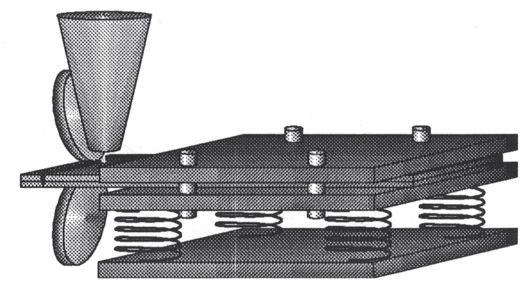
Welding combination fixture with clamping springs (Source: Wikimedia Commons)
Rotary fixtures: Allow rotation of the workpiece to access different welding positions.
Specialised fixtures: Custom-designed for unique or complex components.
Design process for welding fixtures
Analyse the workpiece geometry: Understand shape, size, and weld locations.
Define welding sequence: Determine the order of welds to plan fixture accessibility.
Select fixture type: Choose appropriate fixture based on workpiece and welding method.
Develop clamping strategy: Decide on clamps, stops, and supports.
Incorporate safety features: Ensure operator protection and ergonomic handling.
Review and optimise design: Check for ease of fabrication and cost-effectiveness.
3.1.2 Drawing and specification
Welding fixtures drawings must adhere to recognised standards and clearly specify all details necessary for accurate fabrication and use. The drawing is the only link between the designer and the person who builds the fixture, so anything left out will be guessed. Example: a steel contractor sends a fixture drawing for 50 × 50 mm tube gate frames to its workshop; the drawing states the stop positions, the plate thickness and the tolerance of ±0.5 mm on the frame width, so the fabricator needs no further instructions.
Standards and conventions in welding fixtures drawings
Line types: Use continuous thick lines for visible edges, dashed lines for hidden edges, and centre lines for symmetry (BS EN ISO 128).
Scales: Common scales include 1:1 for small fixtures, 1:2 or 1:5 for larger fixtures (ISO 5455).
Dimensioning: Follow ISO 129 for placement, accuracy, and notation of dimensions.
Symbols: Use welding symbols as per ISO 2553 to indicate weld types related to the fixture.
Title blocks: Include the drawing title, scale, material specification, drawing number, author, and date.
Essential components of welding fixtures drawings
Orthographic views: Front, top, and side views to fully describe the fixture.
Sectional views: Show internal features hidden in orthographic views.
Detail views: Enlarged portions for complex areas like clamping mechanisms.
Material specifications: Indicate fixture material grade and heat treatment if any.
Tolerances: Specify permissible dimensional variations to ensure fit and function.
Specification details in welding fixtures drawings
Clamping force requirements: Define the minimum and maximum force the fixture must apply.
Surface finish: Specify finish quality where the workpiece contacts the fixture.
Welding process compatibility: Indicate if the fixture is suitable for MIG, TIG, or SMAW.
Heat resistance: State maximum operating temperature to select appropriate materials.
Assembly instructions: Provide notes for fixture assembly and component installation.
Common drawing errors to avoid
Omitting critical dimensions: Leads to incorrect fabrication.
Lack of clear welding symbols: Causes confusion in weld requirements.
Poor scale selection: Results in loss of detail or impractical drawing size.
Inconsistent line types: Reduces clarity and professionalism.
Missing material or tolerance notes: Can cause fixture failure or poor fit.
3.1.3 Development of welding fixtures drawing
Drafting welding fixtures drawings is a practical skill that requires methodical application of design principles and standards to produce clear, accurate documents. Development moves from gathering workpiece data, through sketches and formal views, to a checked and approved drawing. Example: a vocational training centre develops a drawing of a fixture for welding 600 mm long angle-iron window frames, starting from a rough sketch and ending with a signed drawing the workshop can use to build the fixture.
Draft and develop welding fixtures drawing
Drafting turns the design decisions made earlier into a set of views, dimensions and notes that another person can build from. The work follows a fixed order so that nothing is missed, and it can be done by hand on a drawing board or on CAD software.
Step-by-step procedure to draft welding fixtures drawing
Gather workpiece data: Obtain detailed dimensions and welding requirements.
Sketch initial layout: Draw rough outline showing fixture positioning relative to the workpiece.
Create orthographic views: Use CAD software or manual drafting tools to produce front, top, and side views.
Add clamping and locating elements: Illustrate clamps, stops, and supports with proper dimensions.
Insert welding symbols and notes: Show weld types and any special instructions.
Apply dimensioning and tolerances: Clearly label all critical measurements and allowable deviations.
Review drawing against standards: Check compliance with BS EN ISO conventions and the drawing standards used by your institution or workshop.
Finalise title block: Complete with drawing number, scale, author, and approval signatures.
CAD tools and equipment specifications for drawing
Name
Specification
Use
CAD software (e.g. AutoCAD)
2D drafting with layers and dimension styles
Drafting detailed fixture drawings
Mechanical pencil
0.5 mm lead, HB grade
Manual sketching and annotations
Drawing board
A1 size with parallel motion ruler
Manual drawing layout
Scale ruler
Metric scales 1:1, 1:2, 1:5
Accurate dimensioning
Eraser
Soft, non-smudging
Correction of manual drawings
Good practice when using these tools:
Maintain CAD libraries: Keep standard fixture components such as clamps, stops and base plates so they can be reused instead of redrawn.
Check instruments: Check scale rules and set squares for damage and trueness regularly, because a worn edge gives wrong dimensions.
Back up digital drawings: Save copies on a second device or drive to avoid data loss.
Use layers: Keep fixture, workpiece, dimensions and notes on separate layers so each can be checked or hidden easily.
Keep drawing surfaces clean: Wipe the board and instruments before starting so that lines stay sharp and prints are not smudged.
Practical tips for developing effective welding fixture drawings
Start with a clear concept: Understand fixture function before drawing.
Show the workpiece in position: Draw the workpiece in thin phantom lines inside the fixture so the builder sees how it is located and clamped.
Keep drawings uncluttered: Use multiple views instead of overcrowding one.
Consult fabricators: Ensure drawings are practical and manufacturable.
Update drawings after feedback: Reflect changes to improve fixture usability.
Quality checks for welding fixtures drawings
Dimension verification: Cross-check all measurements with workpiece data.
Function check: Confirm that the workpiece can be loaded, welded and unloaded without the torch or electrode being blocked.
Clarity and readability: Ensure all text and lines are legible.
Correct use of symbols: Validate welding and dimensioning symbols.
Approval and revision control: Document version history and approvals properly.
Practice Questions
Explain five critical design considerations when creating welding fixtures drawings for a medium-sized fabrication workshop (10 marks)
List and describe six essential components that must appear in a welding fixtures drawing according to ISO standards (12 marks)
Outline the step-by-step procedure to develop a welding fixtures drawing using both manual and CAD methods (15 marks)
Identify common errors in welding fixtures drawings and explain how each can impact the fabrication process (8 marks)
Chapter Summary
This chapter focused on the development of welding fixtures drawings, beginning with the fundamental principles of welding fixture design. It emphasized the importance of creating fixtures that ensure accuracy, repeatability, and efficiency in welding operations. The chapter then covered the detailed process of drawing and specifying welding fixtures, highlighting the need for adherence to relevant standards and clear communication of dimensions and materials. Practical aspects of drafting welding fixtures drawings were explored, guiding students through step-by-step procedures to produce precise and usable technical drawings. Attention was given to the integration of design considerations with drawing conventions to facilitate manufacturing and inspection. By combining theory with hands-on drawing practice, the chapter prepared students to confidently develop complete and professional welding fixtures drawings suitable for industrial application.
What is the primary purpose of a welding fixture in fabrication? (2 marks)
Identify two key design considerations when developing a welding fixture drawing. (2 marks)
Which Kenya Standard (KS) or British Standard (BS) line type is used to represent hidden edges in welding fixture drawings? (2 marks)
List three essential elements that must appear in the title block of a welding fixture drawing. (3 marks)
Explain why dimensional tolerances are critical in welding fixture drawings. (3 marks)
Describe the step-by-step procedure for drafting a basic welding fixture drawing for a rectangular frame. (4 marks)
Which scale is most appropriate for a welding fixture drawing that measures 500 mm by 300 mm for clear presentation on A3 paper? (2 marks)
What symbol is used in welding fixture drawings to indicate a datum reference point? (2 marks)
Explain the difference between a welding jig and a welding fixture. (3 marks)
Why is material specification important in the development of welding fixture drawings? (2 marks)
Show Answers
To securely hold and locate the workpiece during welding to ensure accuracy and repeatability.
Material selection for durability and heat resistance; accessibility for welding and assembly operations.
Dashed lines (short dashes) represent hidden edges according to BS 8888 and KS standards.
Drawing title-scale, drawing number, date, drafter’s name, and revision status.
To ensure parts fit precisely and the fixture functions correctly without misalignment or excessive stress.
(1) Establish drawing scale; (2) sketch base outline; (3) add locating pins and clamps; (4) dimension critical features; (5) add welding symbols; (6) include material notes and title block.
1:2 scale is appropriate to fit the fixture on A3 paper while maintaining clarity.
A triangle symbol or a capital letter inside a triangle marks the datum reference point.
A jig guides the welding tool and controls motion; a fixture holds the workpiece but does not guide the tool.
Material affects strength, thermal expansion, and wear resistance, impacting fixture performance and longevity.
B. Oral Assessment
Discuss how the choice of materials and design features in a welding fixture drawing can impact production efficiency in a manufacturing workshop.
Explain the importance of adhering to drawing standards and conventions when developing welding fixtures drawings for projects such as those at Kenya Railways workshops.
Answer Guide
Question 1 key points:
Material choice affects fixture durability and heat resistance, reducing downtime for repairs.
Design features such as ease of assembly and adjustability improve workflow and reduce setup time.
Proper fixture design ensures repeatability, minimizing rework and improving quality.
Question 2 key points:
Standards ensure clarity and universal understanding among welders and fabricators.
Consistency in line types, symbols, and dimensioning avoids errors during fabrication.
Compliance facilitates quality control and traceability in regulated environments like Kenya Railways.
C. Case Study
At a metal fabrication workshop supplying parts for the Nairobi County Bus Rapid Transit (BRT) project, the engineering team needs to develop welding fixture drawings for a new batch of steel frame assemblies.
Tasks:
a) Draft a welding fixture drawing for a rectangular steel frame measuring 600 mm by 400 mm, including all necessary dimensions and symbols. (10 marks)
b) Specify the material and highlight any critical design features that will ensure accurate welding and ease of use. (5 marks)
c) Explain how you would verify the completed drawing meets KS and BS standards before release. (5 marks)
Suggested Approach
a) Begin by selecting an appropriate scale (e.g., 1:2). Draw the base outline of the frame, add locating pins and clamps positioned to hold the frame securely, and dimension all critical features including hole sizes and distances. Include welding symbols showing the type of weld and finish requirements. Ensure to use correct line types for visible, hidden, and centre lines.
b) Recommend mild steel for its weldability and strength. Design features should include adjustable clamps for variable frame thickness, heat-resistant components near weld zones, and datum points clearly marked for assembly repeatability.
c) Cross-check the drawing against KS and BS standards for line types, dimensioning, symbols, and title block content. Use a checklist to verify all elements are present and correctly applied. Review drawing with a senior engineer for compliance and accuracy before approval.
Chapter Examination Questions
🔒 PDFDownload these examination questions, with worked answers
SECTION A (40 Marks) - Answer ALL Questions
Explain the primary purpose of welding fixtures in a fabrication workshop such as KenGen’s maintenance workshop. (4 marks)
Identify four key design considerations when developing a welding fixture for holding mild steel components. (4 marks)
Describe the role of tolerance and fit in the design of welding fixtures. (4 marks)
List and explain three types of welding fixtures commonly used in structural steel fabrication. (4 marks)
What are the essential elements that must appear in a welding fixture drawing according to BS 8888 standards? (4 marks)
Outline the steps to be followed when drafting a welding fixture drawing using a CAD software. (4 marks)
How does the choice of material for a welding fixture affect its durability and performance? (4 marks)
Explain the importance of specifying welding symbols and annotations on fixture drawings. (4 marks)
Discuss the impact of poor fixture design on weld quality and production efficiency in a Nairobi-based metal fabrication shop. (4 marks)
What is the significance of including a title block and revision history in welding fixture drawings? (4 marks)
Section A - Answers
Welding fixtures ensure accurate positioning and holding of components to maintain alignment and dimensional accuracy during welding, reducing distortion and improving repeatability.
Design considerations include: ease of loading/unloading components, allowance for heat expansion, accessibility for welding torches, and ensuring rigidity to prevent movement.
Tolerance and fit ensure components are held firmly without excessive force, allowing for consistent weld quality and minimizing distortion or misalignment.
Common types: Clamp fixtures (for holding plates), Locating fixtures (for positioning), and Support fixtures (for weight bearing).
Essential elements include: clear dimensioning, welding symbols, material specifications, tolerances, and notes on surface finish.
Steps: set drawing scale, create base views, add dimensions, apply welding symbols, detail components, include title block, and review for compliance.
Materials like cast iron or steel offer strength and heat resistance, enhancing fixture lifespan, while softer materials may deform under heat or pressure.
Welding symbols provide clear instructions for weld type, size, and location, ensuring uniformity and understanding across fabrication personnel.
Poor fixture design may cause misalignment, leading to defective welds, increased rework, and slowed production, negatively affecting profitability.
Title blocks provide essential information (project name, drafter, date), and revision history tracks changes, ensuring version control and traceability.
SECTION B (60 Marks) - Answer any TWO Questions
Question 11 (Compulsory - 20 marks)
At a Nairobi-based metal fabrication company contracted by the Kenya Railways Corporation to produce railcar chassis components:
a) Draft a detailed welding fixture drawing for holding two steel plates at a 90° angle. Include dimensions, welding symbols, and material specifications. (10 marks)
b) Explain how your fixture design facilitates ease of use and ensures weld quality during production. (10 marks)
Question 12 (20 marks)
Describe the procedure for developing a welding fixture drawing from initial concept to final specification, referencing relevant British Standards applicable in Kenya.
Question 13 (20 marks)
Discuss the advantages and limitations of using modular welding fixtures in a Kenyan automotive repair workshop. Provide examples of how these fixtures improve workflow.
Question 14 (20 marks)
Explain how CAD software can be utilized to improve accuracy and efficiency in welding fixture drawings. Include at least three specific CAD features that enhance the design process.
Section B - Answers
Question 11
a) The welding fixture drawing should show two plates held rigidly at a 90° angle using a clamp mechanism, with all relevant dimensions (e.g., plate thickness, clamp size), welding symbols (e.g., fillet weld symbols at joint edges), and material notes (e.g., mild steel grade). The drawing must comply with BS 8888, with clear views (front, side, top) and a title block.
b) The design includes quick-release clamps for fast loading/unloading, robust supports to prevent movement, and accessibility for welding torches, reducing operator fatigue and improving weld consistency.
Question 12
The procedure involves:
Conceptual design based on component geometry and welding requirements
Selecting fixture type and materials
Preparing detailed sketches and layout
Drafting the fixture drawing using CAD, incorporating dimensions, tolerances, welding symbols per BS EN ISO 2553
Reviewing and approving the drawing
Issuing the drawing with specifications for production.
Question 13
Advantages of modular fixtures include flexibility to accommodate different components, reduced setup time, and cost savings over custom fixtures. Limitations include initial investment costs and potential complexity in assembly. In an automotive workshop, modular fixtures allow quick adaptation to different vehicle frames, enhancing workflow efficiency.
Question 14
CAD software improves accuracy by allowing precise dimensioning and scaling, offers simulation of fixture assembly to detect clashes, and facilitates easy revisions with version control. Features like parametric modeling, automated dimensioning, and integrated welding symbol libraries streamline the design process.