
By the end of this chapter, you will be able to:
Mastering these skills will help you become a reliable and skilled professional in mechanical rotor dynamic machines, ready to tackle real-world engineering challenges with confidence.
Mechanical rotor dynamic machines play a crucial role in welding workshops and fabrication plants across Kenya, where fluid handling and pressure management are essential for cooling, lubrication, and hydraulic systems. Understanding the types of pumps used in these environments and their operating principles allows welding professionals to ensure reliable machine performance and prevent downtime. This chapter focuses on the fundamental types of pumps encountered in mechanical rotor dynamic machines, reciprocating and centrifugal pumps, and the derivation of their governing equations for flow and pressure calculations. Mastery of these concepts supports effective maintenance and troubleshooting in welding operations.
The selection of appropriate pumps in welding-related mechanical systems is vital to maintain fluid flow for cooling welding torches, hydraulic lifts, and coolant circulation in fabrication plants. Pumps convert mechanical energy into fluid energy, enabling controlled movement of liquids under pressure. In Kenyan welding workshops, the two predominant pump types are reciprocating and centrifugal pumps, each suited for particular flow and pressure requirements.
Reciprocating pumps operate on a positive displacement principle, where a piston or plunger moves back and forth to draw in and push out fluid. This motion creates alternating suction and delivery strokes, resulting in a pulsating flow. Such pumps are commonly used in welding machine coolant systems where high pressure at low flow rates is required, for example, in precision cooling circuits at large fabrication workshops in Nairobi.
Valve Mechanism: Suction and delivery valves ensure unidirectional flow by opening and closing according to pressure differences during the piston movement.
Pulsating Flow: Due to alternating strokes, the output flow is not continuous but occurs in pulses, necessitating the use of pulsation dampeners in sensitive welding coolant circuits.
Piston/Plunger: Moves to change chamber volume.
Suction Valve: Opens during suction stroke to allow fluid entry.
Connecting Rod: Transmits motion from the crankshaft to the piston.
Crankshaft: Converts rotary motion into reciprocating motion.
Centrifugal pumps operate by converting rotational kinetic energy from an impeller into hydrodynamic energy, producing a continuous flow of fluid. These pumps are widely used in welding workshops for coolant circulation, water supply, and chemical dosing systems due to their ability to handle large volumes at low to medium pressures.
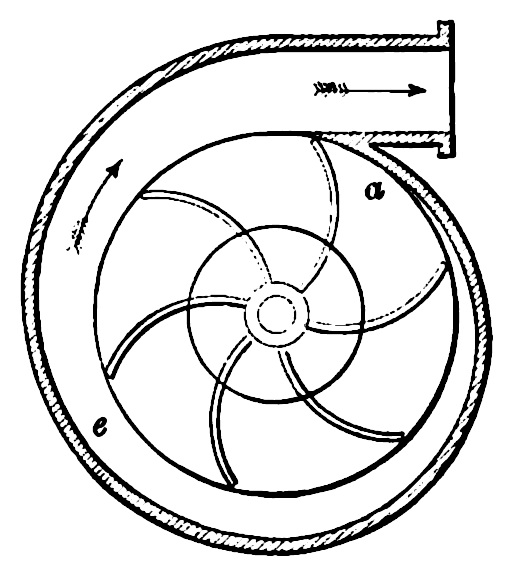
Cross-section of a volute casing with impeller (Source: Wikipedia (Volute (pump)))
Mechanical Seal: Prevents leakage along the shaft.
Bearings: Support the shaft and reduce friction.
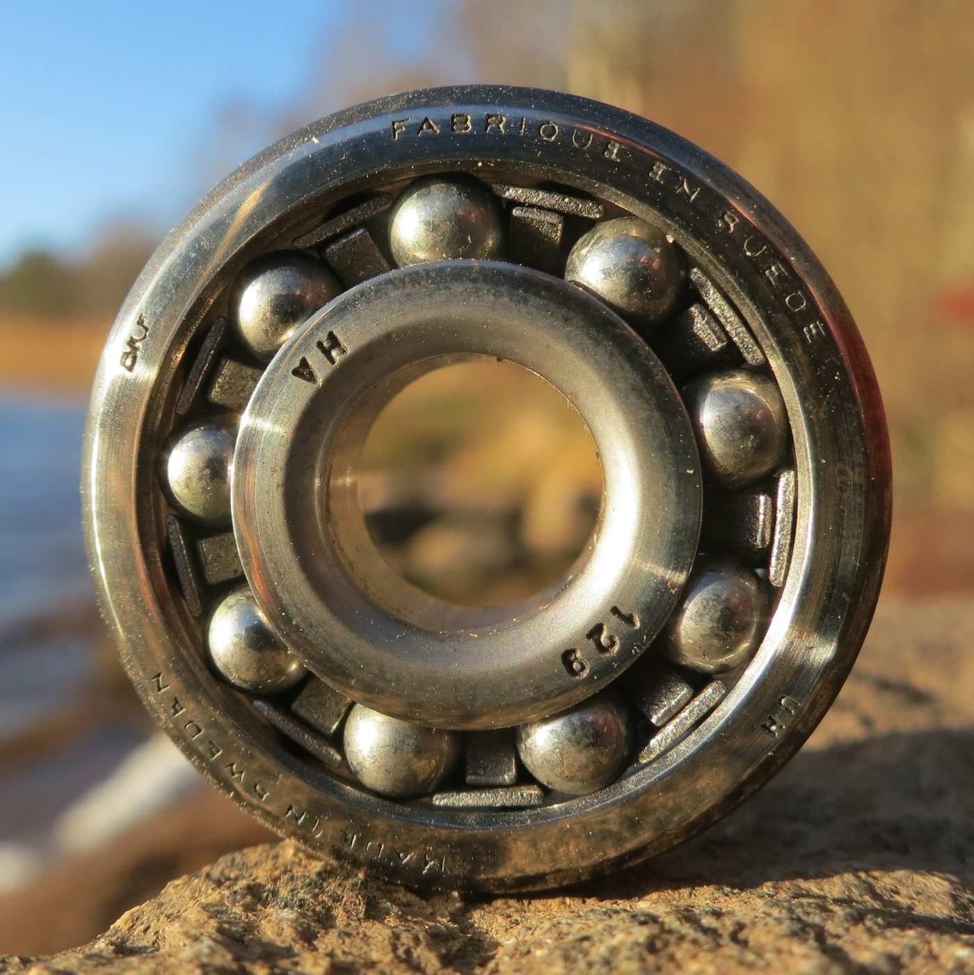
Automotive ball bearing close-up (Source: Wikimedia Commons)
Create a free account to open more of this chapter.
Free: practical guides, quick cards, workplace scenarios and more.
Create a free accountThis chapter explored mechanical rotor dynamic machines with a focus on pumps and compressors. It began by examining the types of pumps, specifically reciprocating and centrifugal pumps, and their operating principles. The chapter then derived key equations related to these pumps, providing a foundation for understanding their mechanical behavior. Analysis techniques for pumps were discussed, covering discharge, efficiency, power, head, and weight per unit to evaluate their performance comprehensively. The study then shifted to rotary compressors, detailing the types such as rotary screw, vane, scroll, and lobe compressors, along with their principles of operation. Further analysis of compressors included parameters like inlet and outlet flow, work done, mass flow rate, power requirements, and efficiency. The structure, functions, and maintenance of compressor fans and vanes were also presented, highlighting their critical role in machine operation. Finally, the chapter concluded with design analysis focusing on vane efficiency, fan efficiency, and power consumption to optimize compressor performance.
Type: Individual
| Tools & Equipment | Materials |
|---|---|
| Allen keys and screwdrivers | Centrifugal pump model |
| Stopwatch | Reciprocating pump model |
| Pressure gauge | Gear pump model |
| Diaphragm pump model | |
| PPE: Safety boots, gloves, overall |
| S/N | Item | Quantity |
|---|---|---|
| 1 | Centrifugal pump model | 1 Pc per Candidate |
| 2 | Reciprocating pump model | 1 Pc per Candidate |
| 3 | Gear pump model | 1 Pc per Candidate |
| 4 | Diaphragm pump model | 1 Pc per Candidate |
| 5 | Set of Allen keys and screwdrivers | 1 Set per Candidate |
| 6 | Stopwatch | 1 Pc per Candidate |
| 7 | Pressure gauge | 1 Pc per Candidate |
| 8 | PPE: Safety boots, gloves, overall | 1 Set per Candidate |
| Items to be Evaluated | Marks Available | Marks Obtained | Comments |
|---|---|---|---|
| TASK 1: Safety and PPE compliance | |||
| Wore safety boots (Award 1 or 0 mark) | 1 | ||
| Wore gloves (Award 1 or 0 mark) | 1 | ||
| Wore overall (Award 1 or 0 mark) | 1 | ||
| Sub-Total | 3 | ||
| TASK 2: Identification of pump types | |||
| Correctly identified centrifugal pump (Award 2 or 0 marks) | 2 | ||
| Correctly identified reciprocating pump (Award 2 or 0 marks) | 2 | ||
| Correctly identified gear pump (Award 2 or 0 marks) | 2 | ||
| Correctly identified diaphragm pump (Award 2 or 0 marks) | 2 | ||
| Sub-Total | 8 | ||
| TASK 3: Demonstration of operation principles | |||
| Demonstrated centrifugal pump operation principle (Award 3 or 0 marks) | 3 | ||
| Demonstrated reciprocating pump operation principle (Award 3 or 0 marks) | 3 | ||
| Demonstrated gear pump operation principle (Award 3 or 0 marks) | 3 | ||
| Demonstrated diaphragm pump operation principle (Award 3 or 0 marks) | 3 | ||
| Used pressure gauge and stopwatch correctly during demonstration (Award 2 or 0 marks) | 2 | ||
| Sub-Total | 14 | ||
| TASK 4: Explanation of pump applications | |||
| Explained typical applications of centrifugal pump (Award 2 or 0 marks) | 2 | ||
| Explained typical applications of reciprocating pump (Award 2 or 0 marks) | 2 | ||
| Explained typical applications of gear pump (Award 2 or 0 marks) | 2 | ||
| Explained typical applications of diaphragm pump (Award 2 or 0 marks) | 2 | ||
| Sub-Total | 8 | ||
| TASK 5: Housekeeping | |||
| Cleaned the work station (Award 1 or 0 mark) | 1 | ||
| Disposed waste correctly (Award 1 or 0 mark) | 1 | ||
| Returned tools and pump models to designated places (Award 1 or 0 mark) | 1 | ||
| Sub-Total | 3 | ||
| PRODUCT CHECKLIST | |||
| Correct identification of all four pump types (Award 1 mark for each correct identification) | 4 | ||
| Clear and accurate demonstration of each pump’s operation principle (Award 2 marks for each pump’s correct demonstration) | 8 | ||
| Accurate explanation of typical applications for each pump type (Award 1 mark for each accurate explanation) | 4 | ||
| Sub-Total | 16 | ||
| GRAND TOTAL | 52 | ||
Type: Individual
| Tools & Equipment | Materials |
|---|---|
| Wrenches set | Cast iron pump body |
| Screwdrivers set | Piston assembly (Ø80mm) |
| Hammer | Connecting rod |
| Feeler gauge | Crankshaft |
| Pressure gauge | Valve assembly set |
| Gasket set | |
| Lubricating oil | |
| Cleaning rags |
| S/N | Item | Quantity |
|---|---|---|
| 1 | Cast iron pump body | 1 Pc per Candidate |
| 2 | Piston assembly (Ø80mm) | 1 Pc per Candidate |
| 3 | Connecting rod | 1 Pc per Candidate |
| 4 | Crankshaft | 1 Pc per Candidate |
| 5 | Valve assembly set (inlet and outlet valves) | 1 Set per Candidate |
| 6 | Gasket set | 1 Set per Candidate |
| 7 | Lubricating oil (500 ml) | 500 ml per Candidate |
| 8 | Wrenches set | 1 Set per 3 Candidates |
| 9 | Screwdrivers set | 1 Set per 3 Candidates |
| 10 | Hammer (1 kg) | 1 Pc per 3 Candidates |
| 11 | Feeler gauge | 1 Pc per 4 Candidates |
| 12 | Pressure gauge (0-10 bar) | 1 Pc per Candidate |
| 13 | Safety boots | 1 Pair per Candidate |
| 14 | Leather gloves | 1 Pair per Candidate |
| 15 | Overall | 1 Pc per Candidate |
| 16 | Safety goggles | 1 Pc per Candidate |
| 17 | Work bench | 1 Pc per 4 Candidates |
| 18 | Cleaning rags | 1 Bundle per Candidate |
| Items to be Evaluated | Marks Available | Marks Obtained | Comments |
|---|---|---|---|
| TASK 1: Safety and PPE Adherence | |||
| Wore safety boots correctly (Award 1 or 0) | 1 | ||
| Wore leather gloves correctly (Award 1 or 0) | 1 | ||
| Wore overall correctly (Award 1 or 0) | 1 | ||
| Wore safety goggles correctly (Award 1 or 0) | 1 | ||
| Sub-Total | 4 | ||
| TASK 2: Preparation and Setup | |||
| Inspected all pump components for defects (Award 1 or 0) | 1 | ||
| Cleaned components before assembly (Award 1 or 0) | 1 | ||
| Set up workbench and tools properly (Award 1 or 0) | 1 | ||
| Applied lubricating oil to moving parts (Award 1 or 0) | 1 | ||
| Sub-Total | 4 | ||
| TASK 3: Assembly of Reciprocating Pump | |||
| Assembled piston and connecting rod correctly (Award 2 or 0) | 2 | ||
| Installed crankshaft with proper alignment (Award 2 or 0) | 2 | ||
| Fitted inlet and outlet valves correctly (Award 2 or 0) | 2 | ||
| Placed gaskets properly to prevent leaks (Award 2 or 0) | 2 | ||
| Tightened all fasteners to specification (Award 2 or 0) | 2 | ||
| Sub-Total | 10 | ||
| TASK 4: Operational Demonstration | |||
| Connected pump to test setup safely (Award 1 or 0) | 1 | ||
| Started pump without unusual noise or vibration (Award 2 or 0) | 2 | ||
| Monitored pressure gauge during operation (Award 2 or 0) | 2 | ||
| Demonstrated smooth piston movement (Award 2 or 0) | 2 | ||
| Stopped pump safely after demonstration (Award 1 or 0) | 1 | ||
| Sub-Total | 8 | ||
| TASK 5: Housekeeping | |||
| Cleaned work area after assembly (Award 1 or 0) | 1 | ||
| Disposed waste materials correctly (Award 1 or 0) | 1 | ||
| Returned tools and unused materials to storage (Award 1 or 0) | 1 | ||
| Sub-Total | 3 | ||
| PRODUCT CHECKLIST | |||
| Assembled pump matches drawing dimensions: 250mm length, 150mm width, 400mm height (Award 5 or 0) | 5 | ||
| Pump operates smoothly with correct piston reciprocation (Award 5 or 0) | 5 | ||
| No leakage from valve or gasket areas during operation (Award 5 or 0) | 5 | ||
| Pressure gauge reading within acceptable operational range (3-6 bar) (Award 3 or 0) | 3 | ||
| All fasteners tight and secure with no loose parts (Award 2 or 0) | 2 | ||
| Sub-Total | 20 | ||
| GRAND TOTAL | 49 | ||
At the start of this chapter we promised you would be able to:
Tick each one you can genuinely do.
So, are you there yet?
You're competent when you can confidently do 50% or more of what this chapter promised.
Sign in to record how you're doing.