Technical drawing is a fundamental skill across all professional fields in Kenya, enabling clear communication of complex objects and systems. Assembly drawings are especially vital for illustrating how individual components fit together to form a complete unit, supporting manufacturing, maintenance, and quality assurance in diverse sectors such as healthcare equipment assembly at county referral hospitals, inventory setups in retail businesses, or machinery installations in agricultural cooperatives. Mastery of orthographic and sectional views ensures precision and clarity, reducing errors and improving operational efficiency.
6.1 Orthographic views of assembly drawings
Orthographic views are the backbone of technical drawing, representing three-dimensional objects in two dimensions with accuracy and clarity. In Kenya’s varied industries from university laboratory equipment to bank security systems, orthographic projections help professionals visualize assemblies without ambiguity. Understanding the difference between first angle and third angle projections is essential as these standards guide how views are arranged and interpreted universally.
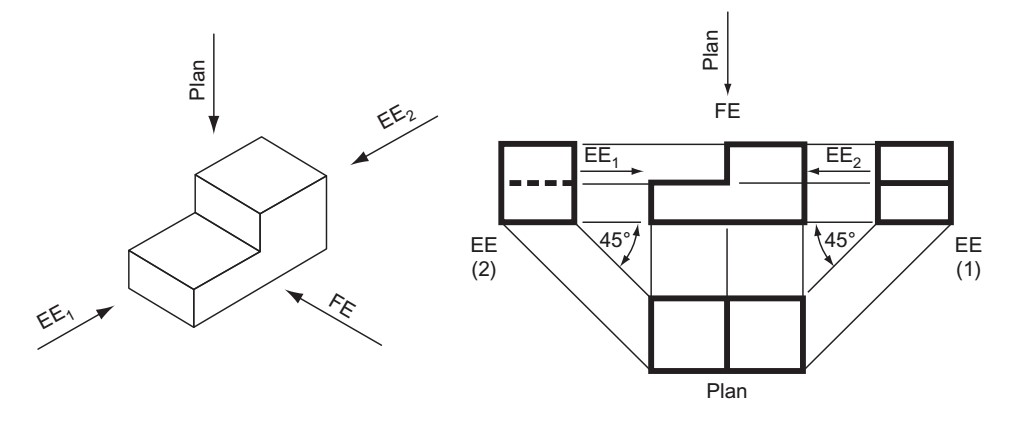
An isometric view and its corresponding orthographic projections (fron (Source: PLUMB 5 LEARNING GUIDE-1 (1))
6.1.1 First angle projection
First angle projection is a method of orthographic drawing widely used in many countries, including Kenya, especially in manufacturing and construction sectors. It involves placing the object between the observer and the projection plane, resulting in specific positioning of views that must be correctly interpreted to avoid costly mistakes.
Meaning of first angle projection
- Projection principle: The object is imagined between the observer and the plane of projection, so views are projected onto planes behind the object.
- View arrangement: The top view is placed below the front view, and the right side view is placed to the left of the front view.
- Visual perspective: This method shows the object as if unfolded around the front view, with each view placed opposite to its actual position.
- International relevance: Commonly used in Europe and many African countries, including Kenya, where British standards influence technical drawing education.
- Application in Kenya: Used in county government offices for architectural plans and in hotel kitchen equipment assembly drawings.
Importance of first angle projection in assembly drawings
- Clear component relationships: Helps visualize how parts fit together from multiple perspectives.
- Standardized communication: Ensures all stakeholders interpret drawings uniformly, reducing errors in production or assembly.
- Facilitates quality control: Enables inspectors to verify assembly accuracy by comparing parts against standard views.
- Supports training: New technicians and artisans learn assembly procedures more effectively with consistent projection methods.
- Cross-sector utility: Applicable in healthcare device assembly at referral hospitals and in cooperative farm machinery layouts.
Steps to construct first angle projection views
- Establish the front view: Begin by drafting the main face of the assembly that best represents its function or appearance.
- Project the top view: Draw projection lines vertically downward from the front view to place the top view below.
- Project the side view: Draw projection lines horizontally to the left from the front view to place the right side view on the left side.
- Add other views if necessary: Include rear or bottom views by projecting appropriately, maintaining the first angle layout.
- Dimension and label: Add measurements and view labels (Front, Top, Right Side) according to BS 8888 or ISO 128 standards.
- Check alignment: Verify that all views align correctly with each other for consistency and ease of interpretation.
Challenges and how to overcome them in first angle projection
Challenges
- Misinterpretation of view placement: Confusion arises because views are opposite to actual object sides.
- Inconsistent training: Some institutions teach third angle projection, leading to mixed understanding.
- Complex assemblies: Large assemblies may require multiple views, complicating layout.
- Scaling issues: Incorrect scaling can distort relationships between views.
- Labeling errors: Missing or incorrect labels confuse users unfamiliar with first angle conventions.
Overcoming challenges
- Standardize training: Ensure all TVET colleges and workplaces adopt consistent teaching of first angle projection.
- Use clear labels: Always mark projection type and view names on drawings.
- Practice with real assemblies: Use equipment from retail businesses or county offices to build familiarity.
- Apply proper scaling: Follow BS EN ISO 5455 for scale selection suited to the assembly size.
- Review and cross-check: Conduct peer reviews and supervisor checks before finalizing drawings.
6.1.2 Third angle projection
Third angle projection is the preferred orthographic method in the United States and increasingly in Kenya's ICT and business sectors, where equipment assemblies require clear and intuitive visual communication. This method places the projection plane between the observer and the object, resulting in a different arrangement of views compared to the first angle projection.
Meaning of third angle projection
- Projection principle: The projection plane is imagined between the observer and the object, so views are projected onto planes in front of the object.
- View arrangement: The top view is placed above the front view, and the right side view is placed to the right of the front view.
- Visual perspective: Views are laid out in the same relative position as on the actual object.
- International relevance: Widely adopted in North America and increasingly in Kenya’s business and ICT sectors.
- Application in Kenya: Used in assembly drawings for security systems in banks and complex ICT hardware setups at universities.
Importance of third angle projection in assembly drawings
- Intuitive interpretation: Views correspond to the actual sides, reducing confusion for users unfamiliar with projections.
- Improved communication: Facilitates clearer instructions in multinational companies operating in Kenya.
- Supports maintenance: Technicians servicing equipment in hotels or hospitals find it easier to locate components.
- Standard compliance: Aligns with ISO and ANSI standards, important for export-oriented manufacturing.
- Versatility: Useful for assemblies ranging from small electronic devices to large retail shelving units.
Steps to construct third angle projection views
- Draw the front view: Begin by depicting the most characteristic face of the assembly.
- Project the top view: Draw projection lines vertically upwards from the front view to place the top view above.
- Project the side view: Draw projection lines horizontally to the right from the front view to place the right side view on the right.
- Add additional views: If required, include rear or bottom views maintaining third angle layout positions.
- Dimensioning and labeling: Apply measurements and clearly mark views according to BS 8888 and ISO 128.
- Verify alignment and scale: Ensure all views are properly aligned and scaled for clarity and accuracy.
Typical mistakes and how to avoid them in third angle projection
Typical mistakes
- Mixing projection methods: Combining first and third angle layouts in one drawing causes confusion.
- Incorrect view placement: Placing top or side views on wrong sides of the front view.
- Omitting labels: Failure to indicate projection type leads to misinterpretation.
- Scaling mismatches: Using inconsistent scales across views distorts assembly understanding.
- Poor dimensioning: Missing or unclear dimensions hinder manufacturing and assembly.
Avoidance strategies
- Adhere strictly to standards: Follow BS 8888 and ISO 128 guidelines for projection and labeling.
- Use templates: Employ drawing templates that enforce correct view placement.
- Educate all team members: Conduct workshops in county government offices and SACCOs to standardize knowledge.
- Implement quality checks: Review drawings for compliance before approval.
- Maintain consistent scales: Use one scale or clearly indicate different scales for various views.
Practice Questions
- Explain the fundamental difference between first angle and third angle projection. (6 marks)
- List the steps to construct the third angle projection of an assembly drawing. (8 marks)
- Identify five common errors in first angle projection drawings and suggest how to correct them. (10 marks)
- Given a simple assembly of a school laboratory stand, sketch the first angle projection views with correct placement of the front, top, and right side views. (10 marks)
The rest of this chapter
🔒Create a free account to open more of this chapter.
Free: practical guides, quick cards, workplace scenarios and more.
Create a free account 🔒6.2 Sectional views
Sectional views reveal internal features of an assembly that are not visible in exterior orthographic views. They are essential in Kenya’s diverse sectors such as hospital equipment manufacturing, retail storage systems, and agricultural machinery, where under…
🔒6.3 Parts list
In the preparation of assembly drawings, the parts list is a critical component that details all individual items making up the assembled product. In Kenya's diverse professional environments, from county hospitals to retail businesses, accurate parts lists en…
Chapter Summary
This chapter focused on producing assembly drawings by exploring key techniques and standards. It began with orthographic views, explaining how assembly components are represented using first angle projection and third angle projection methods, each following specific conventions for layout and interpretation. The chapter then covered sectional views, demonstrating how internal features of assemblies are revealed by cutting through parts to provide clearer understanding of complex structures. Finally, the importance of a parts list was highlighted, showing how it complements assembly drawings by itemizing all components with relevant details such as quantities and descriptions. Mastery of these elements ensures accurate communication of assembly information essential for manufacturing and maintenance. The chapter emphasized adherence to recognized standards to maintain clarity and uniformity in technical drawings. Through understanding these principles, students are equipped to create comprehensive and precise assembly drawings.
Self-Assessment
🔒 PDFDownload this self-assessment, with answers
A. Written Assessment
- What is the main difference between first angle and third angle projection in assembly drawings? (2 marks)
- Identify the correct position of the top view in a first angle projection. (1 mark)
🔒20 more in this section.
Chapter Examination Questions
🔒 PDFDownload these examination questions, with worked answers
SECTION A (40 Marks) - Answer ALL Questions
- Explain the difference between first angle and third angle projection as used in assembly drawings for a county referral hospital’s medical equipment. (4 marks)
- Identify the correct orthographic views needed to fully represent an assembly of a school’s classroom furniture. (4 marks)
🔒23 more in this section.
Chapter Practical Activities
Practical 1: Create orthographic views of a mechanical assembly
Welding Technology · Level 5
Technical Drawing
PRACTICAL ASSESSMENT
TIME: 4 HOURS
⬇ PDFCandidate Instructions (Candidate Tool)
Type: Individual
INSTRUCTIONS TO CANDIDATE:
1. You are required to perform the following task:
i. Produce orthographic views (front, top, and side) of a mechanical assembly measuring 150 mm length, 75 mm width, and 50 mm height as per the provided assembly description.
2. You have been provided with the following resources for the practical task:
| Tools & Equipment | Materials |
|---|
| Drawing board | Assembly drawing brief and parts description |
| T-square | |
| Set squares (45° and 60°) | |
| Mechanical pencil 0.5 mm | |
| Eraser | |
| Compass | |
| Divider | |
| Scale ruler (metric) | |
| Tracing paper A3 size | |
⬇ PDFResources Required (Cutting List)
| S/N | Item | Quantity |
|---|
| 1 | Drawing board | 1 Pc per Candidate |
| 2 | T-square | 1 Pc per Candidate |
| 3 | Set squares (45° and 60°) | 1 Set per Candidate |
| 4 | Mechanical pencil 0.5 mm | 1 Pc per Candidate |
| 5 | Eraser | 1 Pc per Candidate |
| 6 | Compass | 1 Pc per Candidate |
| 7 | Divider | 1 Pc per Candidate |
| 8 | Scale ruler (metric) | 1 Pc per Candidate |
| 9 | Tracing paper A3 size | 2 Sheets per Candidate |
| 10 | Assembly drawing brief and parts description | 1 Set per Candidate |
⬇ PDFAssessor Guide
| Items to be Evaluated | Marks Available | Marks Obtained | Comments |
|---|
| TASK 1: Observe safety and preparation |
Wore appropriate PPE (overall, goggles)
(Award 1 mark or 0 for each) | 2 | | |
Prepared drawing workstation clean and organized
(Award 1 or 0) | 1 | | |
Checked and arranged drawing tools correctly
(Award 1 or 0) | 1 | | |
| Sub-Total | 4 | | |
| TASK 2: Set out and construct orthographic views |
Correctly drew front view with proper scale and proportions
(Award 5 or 0) | 5 | | |
Accurately projected top view aligned with front view
(Award 5 or 0) | 5 | | |
Accurately projected side view aligned with front and top views
(Award 5 or 0) | 5 | | |
Used proper line types (visible, hidden, center) appropriately
(Award 3 or 0) | 3 | | |
Dimensioned views clearly and correctly with tolerances
(Award 4 or 0) | 4 | | |
| Sub-Total | 22 | | |
| TASK 3: Final checks and presentation |
Cleaned drawing surface and erased construction lines
(Award 2 or 0) | 2 | | |
Completed title block and drawing notes as per standards
(Award 3 or 0) | 3 | | |
| Sub-Total | 5 | | |
| PRODUCT CHECKLIST |
Orthographic views dimensioned to 150 mm length, 75 mm width, and 50 mm height with ±1 mm tolerance
(Award 10 or 0) | 10 | | |
Views correctly aligned and proportional
(Award 6 or 0) | 6 | | |
Correct use of line types and symbols
(Award 4 or 0) | 4 | | |
Neatness and clarity of drawing including title block
(Award 3 or 0) | 3 | | |
| Sub-Total | 23 | | |
| GRAND TOTAL | 54 | | |
ASSESSMENT OUTCOME: ☐ Competent ☐ Not Yet Competent (competent if at least 50%)
Practical 2: Produce first angle projection assembly drawing of a mechanical bracket
Welding Technology · Level 5
Technical Drawing
PRACTICAL ASSESSMENT
TIME: 4 HOURS
⬇ PDFCandidate Instructions (Candidate Tool)
Type: Individual
INSTRUCTIONS TO CANDIDATE:
1. You are required to perform the following task:
i. Produce a first angle projection assembly drawing of a mechanical bracket measuring 150 mm length, 100 mm width, and 75 mm height as per the provided working drawing.
2. You have been provided with the following resources for the practical task:
| Tools & Equipment | Materials |
|---|
| Drawing board | Drawing paper A3 size |
| T-square | Set of assembly drawing templates |
| Set squares (45° and 30°/60°) | |
| Protractor | |
| Compass | |
| Pencils (HB, 2H) | |
| Eraser | |
| Scale ruler (metric) | |
⬇ PDFResources Required (Cutting List)
| S/N | Item | Quantity |
|---|
| 1 | Drawing board | 1 Pc per Candidate |
| 2 | T-square | 1 Pc per Candidate |
| 3 | Set squares (45° and 30°/60°) | 1 set per Candidate |
| 4 | Protractor | 1 Pc per Candidate |
| 5 | Compass | 1 Pc per Candidate |
| 6 | Pencils (HB, 2H) | 1 set per Candidate |
| 7 | Eraser | 1 Pc per Candidate |
| 8 | Scale ruler (metric) | 1 Pc per Candidate |
| 9 | Drawing paper A3 size | 2 sheets per Candidate |
| 10 | Set of assembly drawing templates | 1 set per Candidate |
⬇ PDFAssessor Guide
| Items to be Evaluated | Marks Available | Marks Obtained | Comments |
|---|
| TASK 1: Adherence to safety and preparation |
Wore PPE including dustcoat and safety glasses
(Award 1 mark or 0 for each) | 2 | | |
Prepared drawing workspace clean and organized
(Award 1 mark or 0) | 1 | | |
Selected correct drawing tools and materials
(Award 1 mark or 0 for each) | 2 | | |
| Sub-Total | 5 | | |
| TASK 2: Execution of first angle projection drawing |
Correctly set up drawing sheet with title block
(Award 2 or 0) | 2 | | |
Constructed orthographic views using first angle projection method
(Award 1 mark per view, 5 views total) | 5 | | |
Applied correct line types and weights
(Award 1 mark per correct line type) | 3 | | |
| Sub-Total | 10 | | |
| TASK 3: Dimensioning and annotation |
Added all necessary dimensions with correct units and tolerances
(Award 1 mark per dimension, max 5) | 5 | | |
Included appropriate assembly annotations and notes
(Award 1 mark per annotation) | 3 | | |
| Sub-Total | 8 | | |
| TASK 4: Housekeeping |
Left drawing area clean and tools stored properly
(Award 1 mark or 0 for each) | 2 | | |
Disposed of scrap paper as per workplace procedure
(Award 1 mark or 0) | 1 | | |
| Sub-Total | 3 | | |
| PRODUCT CHECKLIST |
Assembly drawing shows length dimension of 150 mm ±1 mm
(Award 3 or 0) | 3 | | |
Assembly drawing shows width dimension of 100 mm ±1 mm
(Award 3 or 0) | 3 | | |
Assembly drawing shows height dimension of 75 mm ±1 mm
(Award 3 or 0) | 3 | | |
Orthographic views are correctly arranged per first angle projection
(Award 4 or 0) | 4 | | |
Dimensions and annotations are clear, legible and correctly placed
(Award 4 or 0) | 4 | | |
| Sub-Total | 17 | | |
| GRAND TOTAL | 43 | | |
ASSESSMENT OUTCOME: ☐ Competent ☐ Not Yet Competent (competent if at least 50%)
🔒Produce third angle projection assembly drawing of a mechanical couplingPractical 3
🔒Draw sectional views of a mechanical assembly to reveal internal featuresPractical 4
🔒Prepare detailed parts list for a mechanical assemblyPractical 5
🔒Produce assembly drawing with first angle projection and sectional viewsPractical 6
🔒Produce Assembly Drawing with Third Angle Projection and Sectional ViewsPractical 7
🔒Create an assembly drawing with parts list using first angle projectionPractical 8
🔒Produce an assembly drawing with parts list using third angle projectionPractical 9
🔒Produce assembly drawing set for a mechanical pump housingPractical 10
