Produce solid geometry drawings plays a crucial role in various Kenyan professional fields by enabling accurate representation of three-dimensional objects on two-dimensional media. Mastery of these drawings facilitates effective communication among architects, designers, quantity surveyors, and technical personnel across sectors such as county government, healthcare infrastructure, education institutions, and commercial enterprises. This chapter focuses on the foundational skills required to sketch and draw patterns of common solid geometrical shapes including cylinders, prisms, and pyramids, ensuring precision and adherence to technical drawing standards.
4.1 Sketches and drawings of patterns
The ability to create sketches and detailed drawings of patterns is essential in diverse Kenyan work environments, ranging from designing packaging for agricultural cooperatives to planning structural elements in county referral hospitals. Patterns serve as templates for manufacturing, construction, and fabrication processes. Understanding the geometric properties and projection methods of solids enables professionals to produce accurate layout plans, which are indispensable in quality control and cost estimation.
4.1.1 Cylinders
Cylinders are widely encountered in engineering, manufacturing, and design tasks, such as creating water tanks for farms or designing structural columns in schools. Proficiency in sketching and drawing cylinders ensures that professionals can visualize and communicate cylindrical components clearly.
Characteristics of Cylinders
- Circular Bases: Cylinders have two parallel circular bases of equal size, crucial for defining their shape in drawings.
- Height: The distance between the two bases, which determines the cylinder’s length in the vertical direction.
- Axis: The straight line joining the centers of the two bases; it serves as the reference for orientation.
- Curved Surface: The lateral surface connecting the two bases, appearing as a rectangle in the development (pattern).
- Symmetry: Cylinders exhibit rotational symmetry around their axis, simplifying projection and pattern development.
Drawing the Orthographic Views of a Cylinder
- Front View: Depicts the height and diameter; it appears as a rectangle with height equal to the cylinder’s height and width equal to the diameter.
- Top View: Shows the circular base as a circle with diameter equal to the cylinder’s base.
- Side View: Identical to the front view due to symmetry.
Developing the Pattern of a Cylinder
- Calculate the circumference: Use the formula Circumference = π × Diameter to determine the length of the rectangle representing the curved surface.
- Draw a rectangle: Width equals the height of the cylinder; length equals the circumference.
- Add two circles: These represent the two bases; ensure their diameter matches the cylinder’s base.
- Mark the joining edges: Indicate where the curved surface connects to the bases for accurate fabrication.
- Include allowances: Add seam and cutting allowances as per manufacturing standards.
Step-by-Step Construction Procedure for a Cylinder Pattern
- Draw the base circle: Using a compass, draw a circle with diameter equal to the cylinder’s base diameter.
- Calculate the circumference: Multiply the diameter by π (3.142) to get the rectangle length.
- Draw the rectangle: Adjacent to the base circle, draw a rectangle with length equal to circumference and width equal to cylinder height.
- Draw the second base circle: At the opposite end of the rectangle, draw another circle identical to the first.
- Mark seam allowance: Draw an edge parallel to the rectangle’s length to indicate seam allowance, typically 5mm.
- Label dimensions: Clearly indicate all relevant dimensions including diameter, height, and allowances.
Practice Questions
- Draw the orthographic views (front, top, side) of a cylinder with a diameter of 100mm and height 150mm. (10 marks)
- Develop a pattern for a cylinder with diameter 80mm and height 120mm, including a seam allowance of 5mm. (15 marks)
- Explain the significance of the axis in cylinder drawings. (5 marks)
4.1.2 Prisms
Prisms appear in numerous professional contexts such as designing beams for county government offices or creating packaging boxes for retail businesses. Understanding prism geometry and drawing techniques is vital for accurate pattern development and fabrication.
Types and Properties of Prisms
-
Right Prism: The lateral edges are perpendicular to the bases; the bases are congruent polygons.
-
Oblique Prism: The lateral edges are not perpendicular to the bases, causing a slanted shape.
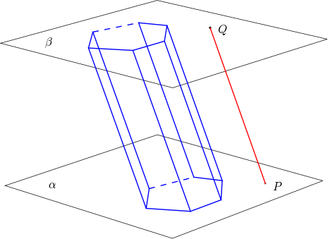
Oblique prism between two planes (Source: Wikimedia Commons)
- Bases: Two parallel faces that are identical polygons, defining the prism’s cross-section.
- Lateral Faces: Rectangles or parallelograms connecting corresponding edges of the bases.
- Height: The perpendicular distance between the bases for right prisms; the shortest distance for oblique prisms.
Orthographic Projection of Prisms
- Front View: Shows the height and shape of one base, usually a rectangle or polygon.
- Top View: Displays the base shape as a polygon.
- Side View: Reveals the prism’s depth and height; for right prisms, it mirrors the front view width.
Developing the Pattern of a Prism
- Identify base shape: Draw the base polygon accurately using geometric construction.
- Calculate perimeter: Sum lengths of all sides of the base polygon; this determines the length of the pattern rectangle.
- Draw lateral rectangle: Length equals base perimeter; width equals prism height.
- Draw base polygons: Two copies, one for each end of the lateral rectangle.
- Mark fold lines: Draw lines where lateral faces join the bases and each other.
- Allow for seam and cutting allowances: Add margins as per fabrication requirements.
Step-by-Step Procedure to Draw a Prism Pattern
- Draw the base polygon: Use ruler and protractor to construct the polygon base with given side lengths and angles.
- Measure perimeter: Add the lengths of all sides to find the total perimeter.
- Draw lateral rectangle: Adjacent to the base, draw a rectangle with length equal to perimeter and width equal to prism height.
- Divide rectangle length: Mark divisions on the rectangle’s length corresponding to each side of the base polygon.
- Draw the second base polygon: At the opposite edge of the rectangle, replicate the base polygon.
- Add seam allowance: Draw a narrow strip parallel to the rectangle’s length for joining edges.
- Label all dimensions: Include side lengths, height, and allowances.
Practice Questions
- Sketch the orthographic views of a right hexagonal prism with side length 30mm and height 100mm. (12 marks)
- Develop the pattern for a right triangular prism with base edges 40mm, 50mm, and 60mm, and height 120mm. Include seam allowance. (15 marks)
- Differentiate between right and oblique prisms with sketches. (8 marks)
4.1.3 Pyramids
Pyramids are encountered in architectural designs and structural elements, such as roofing frameworks for hotels or decorative features in county government buildings. Accurate drawing and pattern development of pyramids are essential for construction and manufacturing.
Properties and Types of Pyramids
- Base Shape: A polygon forming the bottom face; can be triangular, square, or other polygons.
- Apex: The single vertex opposite the base where all triangular faces converge.
- Lateral Faces: Triangular faces connecting the apex to each side of the base.
- Height: The perpendicular distance from the apex to the base plane.
- Slant Height: The length from the apex to the midpoint of a base edge, important in pattern development.
Orthographic Views of Pyramids
- Front View: Shows the height and shape of the pyramid, often a triangle or polygon with apex visible.
- Top View: Displays the base polygon shape.
- Side View: Reveals the lateral triangular faces and height.
Developing the Pattern of a Pyramid
- Draw the base polygon: Construct the base shape accurately.
- Calculate slant heights: Use Pythagoras’ theorem to find slant height if not given.
- Draw triangular lateral faces: Each face is an isosceles triangle with base equal to a side of the base polygon and height equal to the slant height.
- Arrange lateral faces: Draw the triangular faces side by side around the base polygon in the pattern.
- Add seam allowances: Include margins for joining edges.
- Label all dimensions: Include base side lengths, slant height, and allowances.
Step-by-Step Construction Procedure for Pyramid Pattern
- Draw the base polygon: Use geometric tools to construct the exact base shape.
- Determine slant height: Calculate or measure the slant height for each lateral face using height and half base side.
- Draw lateral triangles: For each base edge, draw an isosceles triangle with base equal to the edge and height equal to slant height.
- Arrange lateral triangles: Position the triangles adjacent to each other around the base polygon.
- Add seam allowance: Draw lines parallel to the edges of triangles for seam allowance.
- Label dimensions: Clearly indicate all key measurements including base edges, slant heights, and allowances.
Practice Questions
- Draw the orthographic views of a square pyramid with base side 80mm and height 100mm. (10 marks)
- Develop the pattern for a triangular pyramid with base sides 50mm, 60mm, and 70mm, and height 90mm. Include seam allowance of 5mm. (15 marks)
- Explain how slant height is used in the development of pyramid patterns. (5 marks)
The rest of this chapter
🔒Create a free account to open more of this chapter.
Free: practical guides, quick cards, workplace scenarios and more.
Create a free account 🔒4.2 Solids Drawings
In Kenyan workplaces ranging from county government offices to agricultural cooperatives, the ability to produce clear and accurate solid geometry drawings is essential. These drawings communicate three-dimensional objects on two-dimensional media, facilitatin…
🔒4.3 Development and Interpenetrations of Solids
In many Kenyan industries, from construction at county government offices to product packaging design in retail businesses, understanding how solid objects develop and intersect is crucial. This knowledge assists professionals in visualizing complex assemblies…
🔒4.4 Different symbols and abbreviations
Technical drawings are a language that must be read the same way by the draughtsperson, the fabricator and the inspector. Symbols and abbreviations are the shorthand of that language: they replace long written notes with short, agreed marks and letters so that…
🔒4.5 Auxiliary views and true shapes of truncated solids
A truncated solid is a solid whose top, side or corner has been removed by a cutting plane. When the cutting plane is inclined to the horizontal plane, the cut surface appears as a line in the front view and foreshortened in the plan, so its real size and shap…
Chapter Summary
This chapter focused on producing solid geometry drawings by first exploring the sketching and drawing of basic patterns including cylinders, prisms, and pyramids. It then progressed to detailed solid drawings of prisms, cones, and cylinders, emphasizing accurate construction techniques and dimensioning. The development and interpenetration of solids were covered next, demonstrating how to handle cylinder-to-cylinder, cylinder-to-prism, and prism-to-prism intersections to create precise combined shapes. Various symbols and abbreviations used in technical drawing were introduced to ensure clarity and standardization. The chapter concluded with the use of auxiliary views to reveal true shapes of truncated solids, specifically truncated cylinders, prisms, and pyramids, enabling accurate representation of complex forms. Throughout, the importance of following established standards and step-by-step procedures was emphasized to produce clear, professional drawings.
Self-Assessment
🔒 PDFDownload this self-assessment, with answers
A. Written Assessment
- Which line type is used to represent hidden edges in solid geometry drawings according to BS EN ISO standards? (2 marks)
- Describe the step-by-step procedure to sketch the development of a cylinder. (4 marks)
🔒28 more in this section.
Chapter Examination Questions
🔒 PDFDownload these examination questions, with worked answers
SECTION A (40 Marks) - Answer ALL Questions
- A county referral hospital requires a sketch pattern of a cylindrical oxygen storage tank for maintenance purposes. Describe the steps to create the sketch of the cylinder’s pattern. (4 marks)
- Define a prism and explain how to draw its sketch pattern using a retail business warehouse as a reference. (4 marks)
🔒18 more in this section.
Chapter Practical Activities
Practical 1: Sketch and Draw Patterns of Solids
Welding Technology · Level 5
Technical Drawing
PRACTICAL ASSESSMENT
TIME: 4 HOURS
⬇ PDFCandidate Instructions (Candidate Tool)
Type: Individual
INSTRUCTIONS TO CANDIDATE:
1. You are required to perform the following task:
i. Produce freehand sketches and detailed orthographic drawings of a truncated cone 150 mm diameter base, 80 mm diameter top, and 100 mm height, including its development pattern as per the provided working drawing.
2. You have been provided with the following resources for the practical task:
| Tools & Equipment | Materials |
|---|
| Drawing board | Drawing paper A3 size |
| T-square | |
| Set squares (45° and 60°) | |
| Compass | |
| Divider | |
| Protractor | |
| Pencils (2H, HB, 2B) | |
| Eraser | |
| Scale ruler (300 mm) | |
⬇ PDFResources Required (Cutting List)
| S/N | Item | Quantity |
|---|
| 1 | Drawing board | 1 Pc per Candidate |
| 2 | T-square | 1 Pc per Candidate |
| 3 | Set squares (45° and 60°) | 1 set per Candidate |
| 4 | Compass | 1 Pc per Candidate |
| 5 | Divider | 1 Pc per Candidate |
| 6 | Protractor | 1 Pc per Candidate |
| 7 | Pencils (2H, HB, 2B) | 1 set per Candidate |
| 8 | Eraser | 1 Pc per Candidate |
| 9 | Scale ruler (300 mm) | 1 Pc per Candidate |
| 10 | Drawing paper A3 size | 3 sheets per Candidate |
⬇ PDFAssessor Guide
| Items to be Evaluated | Marks Available | Marks Obtained | Comments |
|---|
| TASK 1: Safety and Preparation |
Wore appropriate personal protective equipment (PPE) such as dustcoat and safety boots
(Award 1 mark each or 0 marks) | 2 | | |
Set up drawing board and arranged tools correctly
(Award 2 marks or 0 marks) | 2 | | |
| Sub-Total | 4 | | |
| TASK 2: Freehand Sketching |
Produced clear and proportionate freehand sketches of the truncated cone
(Award 4 marks or 0 marks) | 4 | | |
Included major views: front elevation, top view, and side elevation
(Award 3 marks or 0 marks) | 3 | | |
| Sub-Total | 7 | | |
| TASK 3: Detailed Drawing and Pattern Development |
Set correct dimensions with linear tolerance ±1 mm
(Award 5 marks or 0 marks) | 5 | | |
Drew orthographic views to scale with neatness and accuracy
(Award 6 marks or 0 marks) | 6 | | |
Developed accurate pattern layout of the truncated cone
(Award 8 marks or 0 marks) | 8 | | |
| Sub-Total | 19 | | |
| PRODUCT CHECKLIST |
Finished drawing shows truncated cone with base diameter 150 mm, top diameter 80 mm, and height 100 mm within ±1 mm tolerance
(Award 6 marks or 0 marks) | 6 | | |
Pattern layout is dimensionally correct and accurately developed
(Award 7 marks or 0 marks) | 7 | | |
Overall neatness, clarity, and completeness of drawings and sketches
(Award 5 marks or 0 marks) | 5 | | |
| Sub-Total | 18 | | |
| GRAND TOTAL | 48 | | |
ASSESSMENT OUTCOME: ☐ Competent ☐ Not Yet Competent (competent if at least 50%)
Practical 2: Technical drawing of a solid cylinder
Welding Technology · Level 5
Technical Drawing
PRACTICAL ASSESSMENT
TIME: 4 HOURS
⬇ PDFCandidate Instructions (Candidate Tool)
Type: Individual
INSTRUCTIONS TO CANDIDATE:
1. You are required to perform the following task:
i. Produce an orthographic drawing of a solid cylinder 80 mm diameter and 120 mm height as per the provided working drawing.
2. You have been provided with the following resources for the practical task:
| Tools & Equipment | Materials |
|---|
| Drawing board | Tracing paper A3 size |
| T-square | |
| Set squares (45° and 60°) | |
| Compass | |
| Divider | |
| French curve | |
| Pencils (H, 2H, HB) | |
| Eraser | |
| Steel ruler (300 mm) | |
⬇ PDFResources Required (Cutting List)
| S/N | Item | Quantity |
|---|
| 1 | Drawing board | 1 Pc per Candidate |
| 2 | T-square | 1 Pc per Candidate |
| 3 | Set squares (45° and 60°) | 1 Set per Candidate |
| 4 | Compass | 1 Pc per Candidate |
| 5 | Divider | 1 Pc per Candidate |
| 6 | French curve | 1 Pc per Candidate |
| 7 | Pencils (H, 2H, HB) | 1 Set per Candidate |
| 8 | Eraser | 1 Pc per Candidate |
| 9 | Steel ruler (300 mm) | 1 Pc per Candidate |
| 10 | Tracing paper A3 size | 3 Sheets per Candidate |
⬇ PDFAssessor Guide
| Items to be Evaluated | Marks Available | Marks Obtained | Comments |
|---|
| TASK 1: Safety and Setup |
Wore appropriate PPE (dust coat, safety boots)
(Award 1 mark each for dust coat and safety boots) | 2 | | |
Set up drawing board and tools correctly
(Award 1 mark each for correct setup of drawing board and tools) | 2 | | |
| Sub-Total | 4 | | |
| TASK 2: Drawing Preparation and Execution |
Used correct drawing scales and instruments
(Award 1 mark each for correct scale and instruments use) | 2 | | |
Laid out construction lines accurately
(Award 1 mark per accurate construction line) | 3 | | |
Completed orthographic views with neatness and clarity
(Award 1 mark each for neatness, clarity, and completeness) | 3 | | |
| Sub-Total | 8 | | |
| TASK 3: Final Checks and Housekeeping |
Verified dimensions and annotations on drawing
(Award 1 mark each for verifying diameter, height, and annotations) | 3 | | |
Cleaned workstation and returned tools
(Award 1 mark each for cleaning and returning tools) | 2 | | |
| Sub-Total | 5 | | |
| PRODUCT CHECKLIST |
Orthographic drawing showing front elevation, top view and side view with diameter 80 mm and height 120 mm dimensioned correctly
(Award 5 marks for correct diameter dimensions, 5 marks for correct height and views) | 10 | | |
Drawing has correct projection, neat lines, and appropriate annotations
(Award 4 marks for projection correctness, 4 marks for line quality and annotations) | 8 | | |
| Sub-Total | 18 | | |
| GRAND TOTAL | 35 | | |
ASSESSMENT OUTCOME: ☐ Competent ☐ Not Yet Competent (competent if at least 50%)
🔒Technical Drawing of Rectangular and Triangular PrismsPractical 3
🔒Produce Technical Drawing of a Square PyramidPractical 4
🔒Drawing a Cone with Specified Base Diameter and HeightPractical 5
🔒Development of Cylindrical Solid Surfaces for FabricationPractical 6
🔒Development Drawing of a Hexagonal PrismPractical 7
🔒Interpenetration of Two Cylinders Solid Geometry DrawingPractical 8
🔒Interpenetration of a Cylinder to a Prism Solid Geometry DrawingPractical 9
🔒Interpenetration of Two Prisms Solid Geometry DrawingPractical 10
🔒Apply correct technical symbols and abbreviations on a solid geometry drawing of a truncated conePractical 11
🔒Drawing Auxiliary Views and True Shapes of a Truncated PyramidPractical 12
🔒Drawing of a Truncated Cylinder to ScalePractical 13
🔒Drawing a Truncated Prism with Specified DimensionsPractical 14
🔒Drawing of a Truncated Square Pyramid with True Shape ViewsPractical 15
