Producing accurate solid geometry drawings is essential for plumbing professionals in Kenya, as these drawings help visualize three-dimensional pipework, fittings, and fixtures in complex installations. Mastery of terminology and concepts in solid geometry ensures that plumbers can interpret and create technical drawings that support effective communication and error-free execution on site. This chapter focuses on the foundational terms and concepts required to understand and produce solid geometry drawings specific to plumbing applications.
3.1 Terms and Concepts
Understanding the fundamental terms and concepts of solid geometry is crucial for plumbing technicians who create and interpret three-dimensional drawings. These concepts enable professionals to visualize plumbing components in space, ensuring correct installation and troubleshooting. This section breaks down the key terminology and ideas that underpin solid geometry drawings in plumbing.
3.1.1 Solid Geometry: Meaning and Scope
Meaning
- Solid geometry is the branch of geometry that deals with three-dimensional figures, encompassing shapes that have length, width, and height.
- It involves the study of volumes, surfaces, edges, and vertices of solids such as cubes, cylinders, cones, and spheres.
- In plumbing, solid geometry helps represent pipes, fittings, valves, and fixtures in three dimensions to provide accurate spatial information.
- It differs from plane geometry, which only studies two-dimensional shapes, by adding the depth dimension critical for real-world plumbing layouts.
- Using solid geometry drawings, plumbers can visualize how different components fit together in confined spaces such as bathrooms or underground.
Scope
- Solid geometry covers the construction, measurement, and representation of 3D shapes relevant to plumbing systems.
- It includes the understanding of intersections, cross-sections, and projections of solid objects like pipes crossing or joining at angles.
- The scope extends to the creation of isometric and orthographic projections that convey the spatial arrangement of plumbing installations.
- It involves calculations of volumes and surface areas important for material estimation and flow dynamics in plumbing systems.
- Solid geometry also informs the use of CAD software and manual drawing techniques for creating precise plumbing diagrams.
3.1.2 Types of Solids Common in Plumbing Drawings
Prismatic Solids
- Prismatic solids have two identical parallel faces connected by rectangular faces, such as rectangular ducts or box-shaped tanks.
- They are used to represent plumbing components like water tanks, rectangular gutters, or inspection chambers.
- The parallel faces simplify the projection and measurement of lengths and widths in drawings.
- Prismatic solids often form the basis of isometric drawings where edges remain parallel and proportional.
- Understanding their properties helps in accurately scaling and dimensioning plumbing elements.
Cylindrical Solids
- Cylindrical solids are shaped like pipes and tubes, with circular cross-sections and uniform diameter along their length.
- Pipes, conduit sleeves, and certain types of valves are represented as cylinders in plumbing drawings.
- Their curved surfaces require careful representation in projections to avoid distortion.
- Cylindrical solids often intersect with other solids, requiring knowledge of intersection geometry for accurate depiction.
- Mastery of cylinders in drawings is essential for visualizing complex pipe networks and connections.
Conical and Spherical Solids
- Conical solids taper from a circular base to a point, representing components like funnels or certain types of reducers.
- Spherical solids represent ball valves or spherical tanks used in plumbing systems.
- These shapes require advanced understanding of curves and surface generation for accurate rendering.
- Their inclusion in drawings adds realism and precision to plumbing designs, especially in valves and fittings.
- Recognizing these solids helps plumbers identify the function and installation requirements of such components.
3.1.3 Fundamental Elements of Solid Geometry Drawings
Vertices
- Vertices are points where edges of a solid meet, forming the corners of the shape.
- In plumbing drawings, vertices define the junctions of pipes or fittings.
- Accurate placement of vertices ensures correct representation of component intersections.
- They serve as reference points for dimensioning and scaling drawings.
- Errors in vertex positioning can lead to misalignment of plumbing elements in installation.
Edges
- Edges are the line segments connecting vertices, representing the boundaries of faces on a solid.
- In plumbing, edges illustrate the lengths and connections of pipes and fittings.
- Correct edge representation helps in visualizing the continuity of pipe runs.
- Edges also define the outline of components in projections and sections.
- Understanding edges is critical for identifying pipe bends, joints, and transitions in drawings.
Faces
- Faces are flat or curved surfaces bounded by edges, forming the external surfaces of solids.
- Plumbing components such as tanks or ducts are represented by their faces in drawings.
- Faces provide information about the shape and orientation of plumbing elements.
- Different faces may be visible or hidden depending on the viewing angle in the drawing.
- Identifying faces helps in the application of surface treatments or insulation specifications.
3.1.4 Projection Methods Relevant to Solid Geometry in Plumbing
Isometric Projection
- Isometric projection is a method of visually representing three-dimensional objects in two dimensions, where the three axes are equally inclined at 120 degrees.
- It preserves the scale along each axis, allowing accurate measurements directly from the drawing.
- In plumbing, isometric drawings depict pipe runs and fittings in a single view, facilitating easier interpretation.
- This method aids in visualizing complex pipe networks without distortion of angles.
- Isometric drawings are widely used in plumbing installation plans and fabrication drawings.
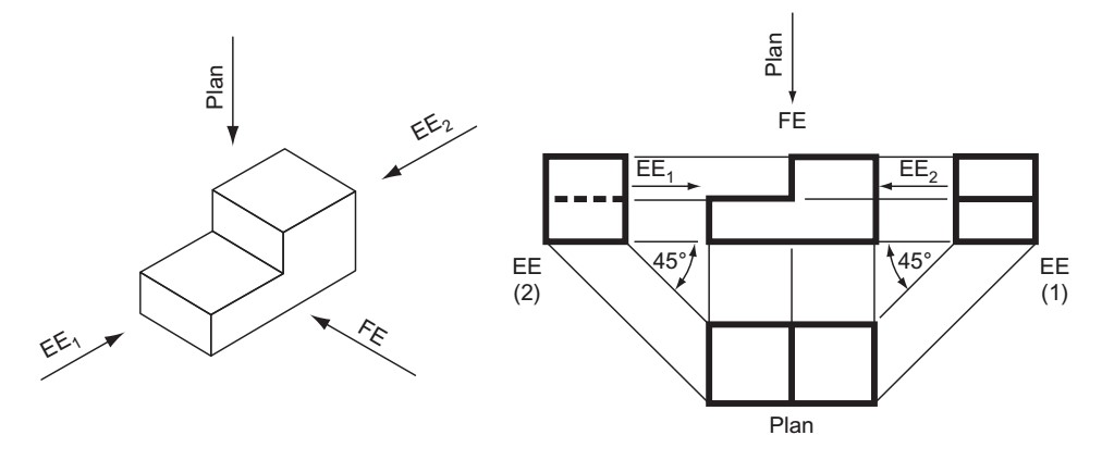
An isometric view and its corresponding orthographic projections (fron (Source: PLUMB 5 LEARNING GUIDE-1 (1))
Orthographic Projection
- Orthographic projection represents solids using multiple views, typically front, top, and side elevations.
- Each view shows the object from a perpendicular angle, providing precise dimensions and shape details.
- Plumbing professionals use orthographic projections to detail component dimensions and installation points.
- It is essential for producing working drawings that guide fabrication and assembly.
- Orthographic drawings complement isometric views by providing exact measurements and specifications.
Sectional Views
- Sectional views cut through solids to expose internal features not visible in external views.
- In plumbing, sectional drawings reveal pipe interiors, valve mechanisms, or hidden joints.
- These views help in understanding the internal arrangement and maintenance requirements.
- Sectional views use standard cutting-plane lines and hatching conventions to indicate cut surfaces.
- They are critical for troubleshooting and repair planning in plumbing systems.
Practice Questions
- Define solid geometry and explain its significance in plumbing technical drawings. (6 marks)
- Describe the differences between prismatic and cylindrical solids with examples relevant to plumbing. (8 marks)
- Identify and explain the roles of vertices, edges, and faces in a plumbing solid geometry drawing. (9 marks)
- Compare isometric and orthographic projections and discuss when each is used in plumbing. (7 marks)
The rest of this chapter
🔒Create a free account to open more of this chapter.
Free: practical guides, quick cards, workplace scenarios and more.
Create a free account 🔒3.2 Interpretation of sketches and drawings of patterns e.g. cylinders, prisms and pyramids
In plumbing practice across Kenya, the ability to interpret sketches and technical drawings of solid geometrical patterns such as cylinders, prisms, and pyramids is essential. These shapes often represent components like pipes, ducts, tanks, and connectors in…
🔒3.3 Develop geometrical solid figures e.g. prisms, cones-truncated
In plumbing technical drawing, the ability to accurately develop geometrical solids such as prisms, cones, and truncated shapes is essential. These shapes represent pipes, fittings, tanks, and other plumbing components that require precise representation for f…
🔒3.4 Surface development
Surface development is a fundamental skill in plumbing technical drawing, enabling professionals to create accurate flat patterns from three-dimensional solids. In Kenya’s plumbing industry, surface development is crucial for fabricating ducts, pipes, tanks, a…
Chapter Summary
This chapter introduced key terms and concepts essential for understanding solid geometry in technical drawing, providing a foundation for accurate representation. It covered the interpretation of sketches and drawings of common solid patterns such as cylinders, prisms, and pyramids, enabling clear visualization of three-dimensional objects. The process of developing geometrical solid figures including prisms, cones, and truncated solids was explained with step-by-step construction methods. Emphasis was placed on the importance of precise measurements and adherence to drawing standards throughout. The chapter also detailed surface development techniques, showing how to unfold solid figures onto a plane for accurate pattern creation. By mastering these topics, learners can produce comprehensive and accurate solid geometry drawings critical for practical applications in engineering and design.
Self-Assessment
🔒 PDFDownload this self-assessment, with answers
A. Written Assessment
- Define the term prism in the context of solid geometry. (2 marks)
- Which type of line is used to represent hidden edges in plumbing technical drawings according to BS 8888?
a) Continuous thick line
b) Dashed line
c) Chain line
d) Thin continuous line (2 marks)
🔒20 more in this section.
Chapter Examination Questions
🔒 PDFDownload these examination questions, with worked answers
SECTION A (40 Marks) - Answer ALL Questions
- Define the term truncated cone and explain its relevance in plumbing pipe fittings. (4 marks)
- Identify the main differences between a prism and a cylinder in solid geometry drawings used in plumbing systems. (4 marks)
🔒30 more in this section.
Chapter Practical Activities
Practical 1: Identify and Explain Key Solid Geometry Terms
Plumbing · Level 5
Technical Drawing
PRACTICAL ASSESSMENT
TIME: 3 HOURS
⬇ PDFCandidate Instructions (Candidate Tool)
Type: Individual
INSTRUCTIONS TO CANDIDATE:
1. You are required to perform the following task:
i. Identify and verbally explain five key solid geometry terms using models and sketches on A3 drawing paper.
2. You have been provided with the following resources for the practical task:
| Tools & Equipment | Materials |
|---|
| Pencil HB | Solid geometry models (cube, sphere, cone, cylinder, pyramid) |
| Eraser | Drawing paper A3 size |
| Ruler 300 mm | |
| Protractor 180 degrees | |
| Set square (45 and 60 degrees) | |
⬇ PDFResources Required (Cutting List)
| S/N | Item | Quantity |
|---|
| 1 | PPE (helmet, gloves, dustcoat) | 1 full set per Candidate |
| 2 | Solid geometry models (cube, sphere, cone, cylinder, pyramid) | 1 set per Candidate |
| 3 | Drawing paper A3 size | 2 sheets per Candidate |
| 4 | Pencil HB | 2 Pcs per Candidate |
| 5 | Eraser | 1 Pc per Candidate |
| 6 | Ruler 300 mm | 1 Pc per Candidate |
| 7 | Protractor 180 degrees | 1 Pc per Candidate |
| 8 | Set square (45 and 60 degrees) | 1 set per Candidate |
⬇ PDFAssessor Guide
| Items to be Evaluated | Marks Available | Marks Obtained | Comments |
|---|
| TASK 1: Use of PPE and Preparation |
Wore PPE (helmet, gloves, dustcoat) as per OSHA regulations
(Award 1 mark if all PPE worn, zero if not) | 1 | | |
Prepared drawing materials and tools correctly
(Award 1 mark if all tools and materials are ready and correctly arranged) | 1 | | |
| Sub-Total | 2 | | |
| TASK 2: Identification and Explanation of Solid Geometry Terms |
Identified at least five solid geometry terms correctly (e.g., vertex, edge, face, base, apex)
(Award 1 mark for each correctly identified term, up to 5 marks) | 5 | | |
Provided clear verbal explanations of the identified terms using models or sketches
(Award 1 mark for each clear and correct explanation, up to 5 marks) | 5 | | |
| Sub-Total | 10 | | |
| TASK 3: Sketching and Demonstration |
Sketched representations of the solid geometry terms clearly on drawing paper
(Award up to 3 marks for clarity, accuracy, and neatness of sketches) | 3 | | |
Demonstrated correct use of tools in sketching (ruler, protractor, set square)
(Award 2 marks for correct and safe use of drawing tools) | 2 | | |
| Sub-Total | 5 | | |
| PRODUCT CHECKLIST |
Five solid geometry terms identified and explained correctly
(Award 1 mark for each correctly identified and explained term) | 5 | | |
Accurate and neat sketches of the terms on A3 drawing paper
(Award up to 5 marks for accuracy, neatness, and completeness of sketches) | 5 | | |
| Sub-Total | 10 | | |
| GRAND TOTAL | 27 | | |
ASSESSMENT OUTCOME: ☐ Competent ☐ Not Yet Competent (competent if at least 50%)
Practical 2: Interpret and Produce Scaled Technical Drawings of a Cylinder and Prism
Plumbing · Level 5
Technical Drawing
PRACTICAL ASSESSMENT
TIME: 4 HOURS
⬇ PDFCandidate Instructions (Candidate Tool)
Type: Individual
INSTRUCTIONS TO CANDIDATE:
1. You are required to perform the following task:
i. Produce scaled orthographic drawings (front elevation, top view, and side elevation) of a cylinder with diameter 80mm and height 150mm, and a right rectangular prism 100mm wide, 80mm deep, and 150mm high as per the provided sketches.
2. You have been provided with the following resources for the practical task:
| Tools & Equipment | Materials |
|---|
| Mechanical pencil | Drawing sheet A3 size |
| Eraser | |
| Set squares | |
| Compass | |
| Protractor | |
| Scale ruler | |
| Technical drawing templates | |
⬇ PDFResources Required (Cutting List)
| S/N | Item | Quantity |
|---|
| 1 | Drawing sheets A3 size | 1 Sheet per Candidate |
| 2 | Mechanical pencils (0.5mm) | 1 Pc per Candidate |
| 3 | Eraser | 1 Pc per Candidate |
| 4 | Set squares (45° and 60°) | 1 Set per Candidate |
| 5 | Compass | 1 Pc per Candidate |
| 6 | Protractor | 1 Pc per Candidate |
| 7 | Scale ruler (metric) | 1 Pc per Candidate |
| 8 | Technical drawing templates (circle and ellipse templates) | 1 Pc per Candidate |
⬇ PDFAssessor Guide
| Items to be Evaluated | Marks Available | Marks Obtained | Comments |
|---|
| TASK 1: Interpretation and Drawing Preparation |
Used personal protective equipment (PPE) such as dustcoat and safety glasses
(Award 1 mark if PPE worn correctly or zero) | 1 | | |
Interpreted the provided sketches accurately identifying cylinder and prism dimensions
(Award 1 mark for each correct interpretation: cylinder dimensions, prism dimensions, and views) | 3 | | |
Set out drawing sheet with correct title block and scale (1:1 or 2:1 as appropriate)
(Award 2 marks for correct title block and scale, zero otherwise) | 2 | | |
Used drawing tools correctly (compass, set squares, scale ruler, templates)
(Award 1 mark for correct use of each tool category or zero) | 3 | | |
| Sub-Total | 9 | | |
| TASK 2: Drawing Execution |
Drew front elevation of cylinder with correct diameter and height
(Award 3 marks for neatness and accuracy matching 80mm diameter and 150mm height) | 3 | | |
Drew top view of cylinder as a circle with correct diameter
(Award 2 marks for correct 80mm diameter circle) | 2 | | |
Drew side elevation of prism with correct width, depth and height
(Award 4 marks for correct dimensions: 100mm width, 80mm depth, 150mm height) | 4 | | |
Drew top view of prism showing correct width and depth
(Award 2 marks for accurate rectangle 100mm x 80mm) | 2 | | |
Applied correct line types (visible, hidden, centre lines) as per technical drawing standards
(Award 3 marks for correct line types and neatness) | 3 | | |
| Sub-Total | 14 | | |
| PRODUCT CHECKLIST |
Finished drawings show cylinder with diameter 80mm and height 150mm with front, top, and side views
(Award 5 marks for accurate dimensions and views) | 5 | | |
Finished drawings show rectangular prism with width 100mm, depth 80mm, height 150mm with front, top, and side views
(Award 5 marks for accurate dimensions and views) | 5 | | |
Drawings are neat, correctly scaled, and conform to technical drawing standards
(Award 6 marks for overall presentation, line quality, and adherence to standards) | 6 | | |
| Sub-Total | 16 | | |
| GRAND TOTAL | 39 | | |
ASSESSMENT OUTCOME: ☐ Competent ☐ Not Yet Competent (competent if at least 50%)
🔒Interpretation and Drawing of a Square Pyramid PatternPractical 3
🔒Develop surface layout of a hexagonal prismPractical 4
🔒Develop surface layout of a cone 150mm diameter base x 300mm heightPractical 5
🔒Develop Surface Layout of a Truncated PyramidPractical 6
🔒Freehand Sketching of Basic Solid Geometry FiguresPractical 7
🔒Draw Orthographic Views of a Hexagonal PrismPractical 8
🔒Assemble a paper model of a truncated pyramid from developed surfacesPractical 9
🔒Comparison and Analysis of Solid Geometry Surface DevelopmentsPractical 10
