3.1 Electrical components
3.1.1 Junction boxes
Junction boxes serve as protective enclosures where electrical connections are made, safeguarding wiring from environmental damage and unauthorized access. Their role is critical in organizing cable networks within buildings, facilitating maintenance and future modifications without compromising safety. In institutions like county government offices, junction boxes are strategically placed to ensure neat wiring runs and easy troubleshooting.
Purpose of Junction Boxes
- Protection of Connections: Junction boxes shield wire splices and terminals from dust, moisture, and mechanical damage, reducing the risk of short circuits and electrical fires.
- Organization of Wiring: They enable systematic joining of multiple cables, preventing tangled or exposed wires that could cause hazards or complicate repairs.
- Facilitating Maintenance: By centralizing connections, junction boxes allow electricians to isolate and inspect circuits without dismantling walls or ceilings.
- Compliance with Standards: Installation of junction boxes is a legal requirement under Kenyan electrical regulations to ensure installations meet safety codes.
- Support for Circuit Expansion: Junction boxes provide accessible points for extending wiring circuits when additional outlets or devices are added in buildings like universities or retail outlets.
Types of Junction Boxes
- Metallic Boxes: Made from steel or aluminum, these boxes offer robust mechanical protection and are grounded to prevent electrical shock.
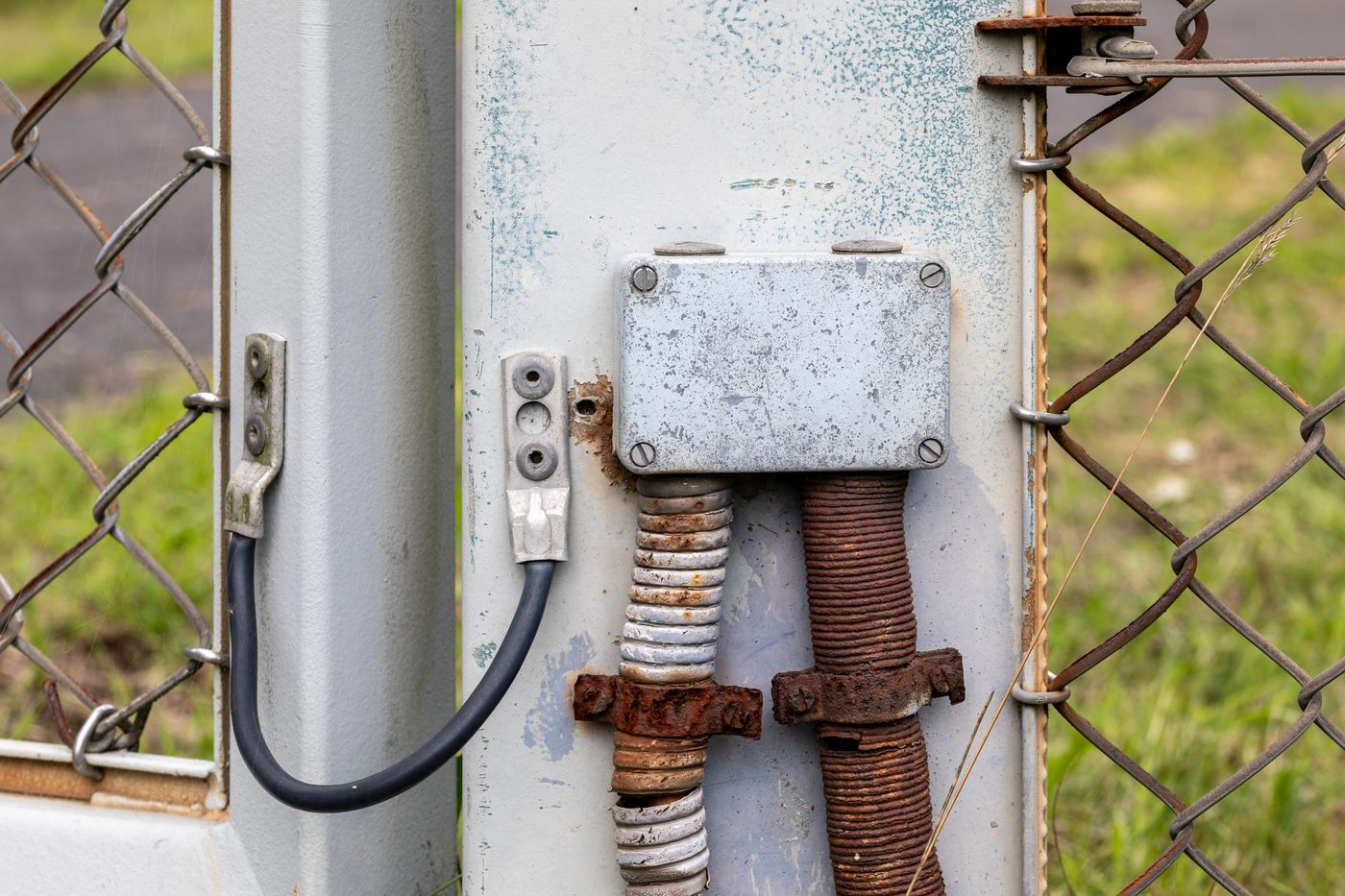
metallic electrical junction box on a fence post (Source: Wikimedia Commons)
- Plastic Boxes: Lightweight and corrosion-resistant, plastic junction boxes are common in dry indoor environments such as office buildings.
- Surface-mounted Boxes: Installed on walls or ceilings, these are suitable for retrofitting or where embedding in walls is impractical.
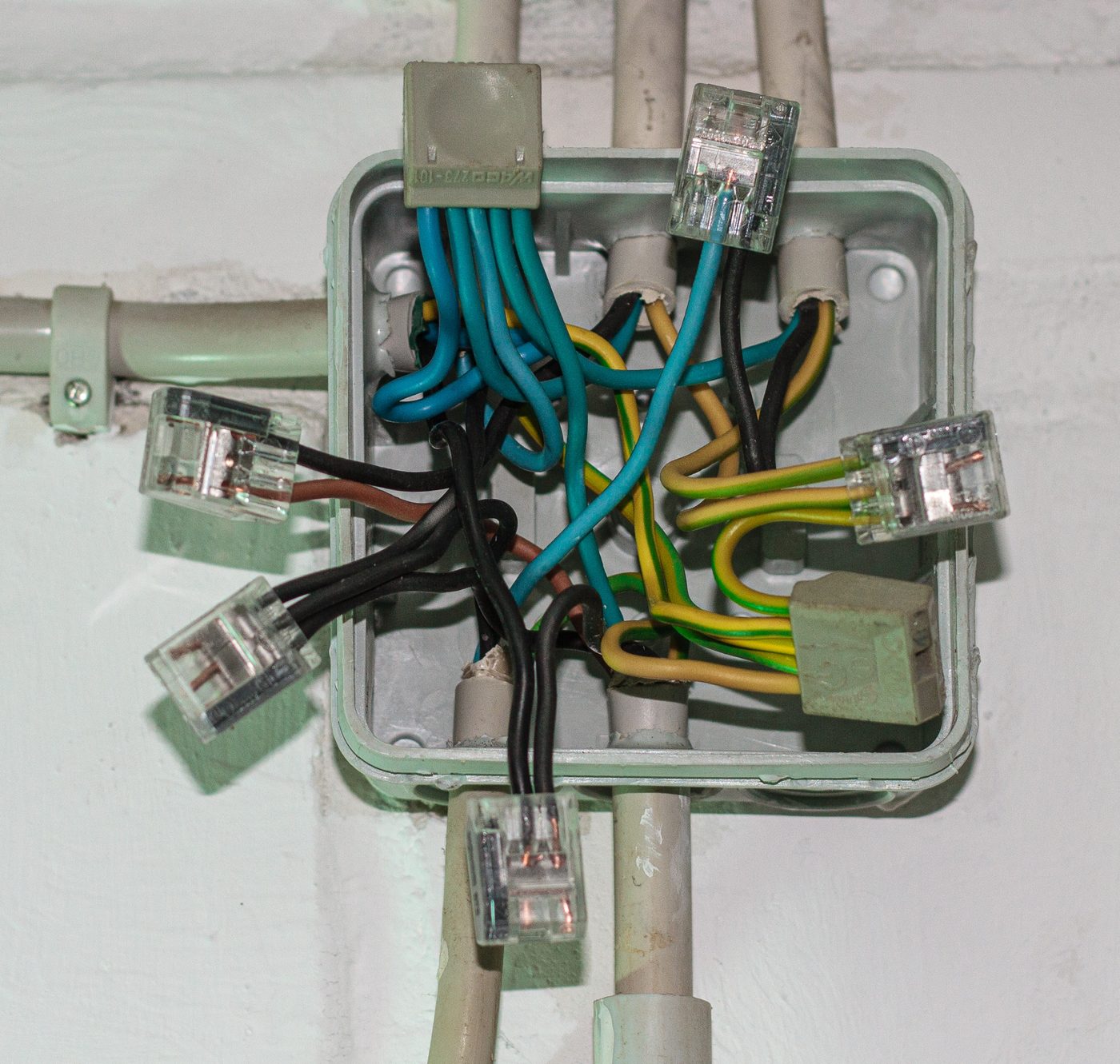
Surface-mounted electrical junction box with wiring (Source: Wikimedia Commons)
- Flush-mounted Boxes: Recessed into walls or ceilings for aesthetic integration and protection, commonly used in hospitals and schools.
- Weatherproof Boxes: Designed with sealed covers and gaskets, these boxes protect outdoor connections from rain and dust, essential in agricultural or rural installations.
Installation Considerations for Junction Boxes
- Accessibility: Boxes should be positioned for easy access during inspections or repairs, avoiding concealed or obstructed locations.
- Adequate Size: The box must accommodate all wires and connectors without overcrowding to prevent overheating and mechanical stress.
- Proper Earthing: Metallic boxes require reliable grounding to prevent electric shock hazards.
- Secure Fixing: Boxes should be firmly fixed to structural elements to avoid movement that could loosen connections.
- Use of Appropriate Covers: Covers must fit tightly to prevent ingress of dirt and moisture, maintaining long-term safety.
Maintenance of Junction Boxes
- Periodic Inspection: Regular checks for corrosion, loose connections, or signs of overheating help prevent faults.
- Cleaning: Removing dust and debris from inside the box maintains good contact and prevents fire risks.
- Replacement of Damaged Components: Damaged terminals or boxes must be replaced promptly to ensure system integrity.
- Verification of Earth Continuity: Ensuring metallic boxes remain properly earthed is critical for personnel safety.
- Documentation: Keeping records of junction box locations and wiring diagrams aids future troubleshooting and expansions.
3.1.2 Ceiling rose
The ceiling rose is an essential component for connecting lighting fixtures to the electrical supply, providing both mechanical support and electrical connection points. In Kenyan hotels and retail businesses, ceiling roses are integral to the aesthetic and functional installation of lighting systems, ensuring safe and reliable operation.
Function and Design of Ceiling Roses
- Electrical Connection Point: Ceiling roses provide terminals for live, neutral, and earth wires to connect lighting fixtures safely.
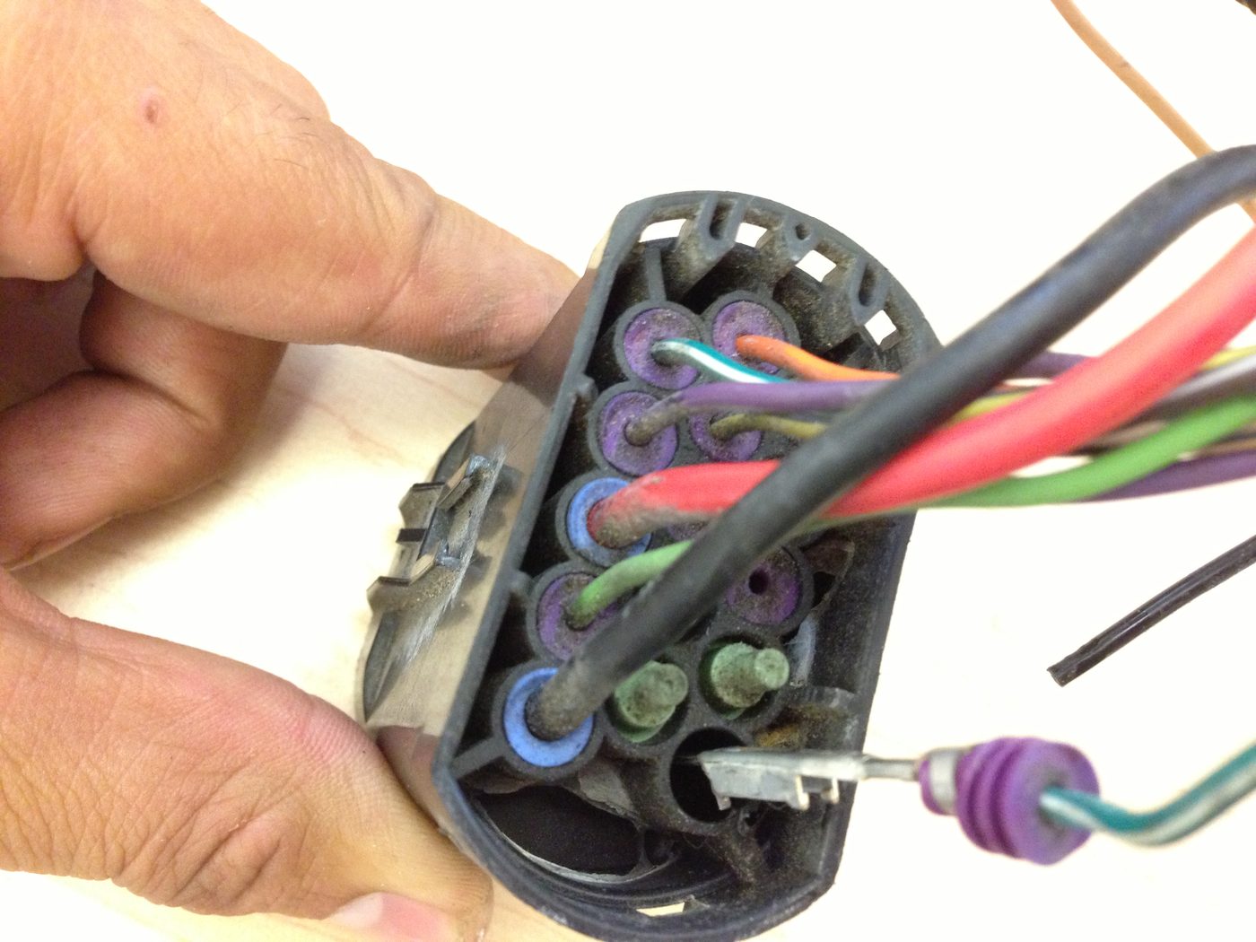
Electrical connection point with multiple wires (Source: Wikimedia Commons)
- Mechanical Support: They secure the weight of the light fitting, preventing strain on electrical cables.
- Aesthetic Integration: Ceiling roses often have decorative covers that blend with interior finishes, enhancing visual appeal.
- Standardized Fixing: Designed to fit common electrical boxes, ceiling roses facilitate standardized installations across different buildings.
- Safety Features: Many ceiling roses include built-in fuses or switches to protect circuits and allow convenient control.
Types of Ceiling Roses
- Standard Ceiling Roses: Basic models used in residential and commercial premises for simple light fixtures.
- Switched Ceiling Roses: Incorporate a built-in switch to control the light directly at the fitting, useful in hotels and guest houses.
- Fused Ceiling Roses: Include a fuse for circuit protection, often used where additional safety measures are required.
- Decorative Ceiling Roses: Feature ornamental designs for upscale environments such as conference centers or university halls.
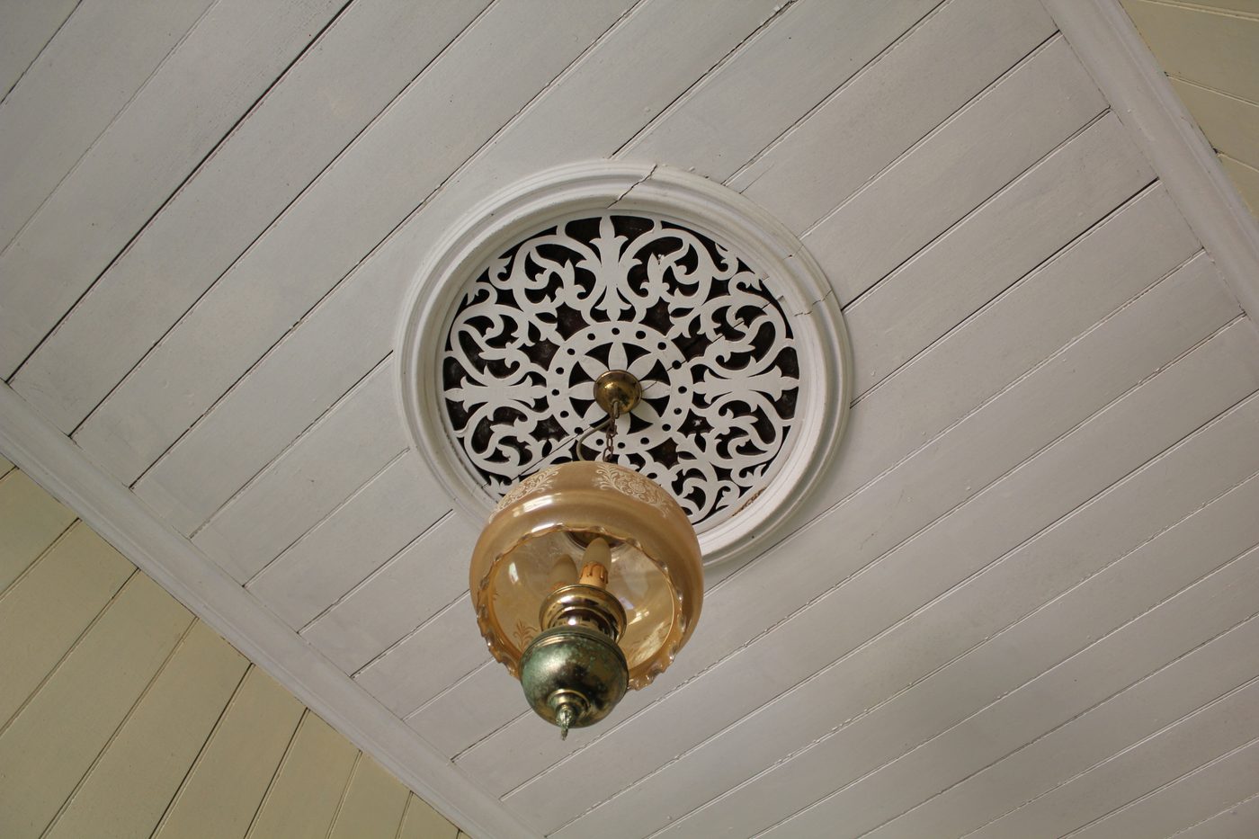
Decorative ceiling rose with hanging light fixture (Source: Wikimedia Commons)
- Multiple Outlet Roses: Provide connections for more than one light fitting or device from a single ceiling point.
Installation Best Practices for Ceiling Roses
- Secure Mounting: The rose must be firmly fixed to a ceiling box or joist to support the light fitting's weight.
- Proper Wiring: Correct identification and connection of live, neutral, and earth wires prevent faults and hazards.
- Compliance with Polarity: Ensuring the live wire connects to the appropriate terminal avoids electrical shock risks.
- Use of Insulated Connectors: Protects against short circuits and improves durability of connections.
- Test Before Final Fixing: Verifying electrical continuity and polarity before fixing the rose cover ensures safety.
Maintenance and Troubleshooting
- Checking for Loose Connections: Loose terminals in ceiling roses can cause flickering lights or overheating.
- Replacing Damaged Roses: Cracked or broken roses must be replaced to maintain electrical safety.
- Cleaning Dust and Debris: Accumulated dirt can degrade insulation and cause faults.
- Inspecting Switch Mechanisms: For switched ceiling roses, ensuring the switch operates smoothly prevents electrical arcing.
- Verifying Earthing: Confirming earth continuity protects users from electric shock.
3.1.3 Switches
Switches control the flow of electricity to lighting and appliances, forming a critical interface between users and electrical systems. In banks and SACCO offices, reliable switches contribute to operational efficiency and safety by allowing controlled power distribution.
Purpose and Function of Switches
- Control of Electrical Circuits: Switches enable users to open or close circuits, turning devices on or off.
- Safety Mechanism: They allow isolation of electrical devices for maintenance or emergency shutdown.
- Energy Conservation: By switching off unused devices, switches help reduce energy consumption.
- User Convenience: Switches are positioned for easy access to control lighting and equipment.
- Integration with Automation: Modern switches can interface with smart systems for remote control and monitoring.
Types of Switches
- Single-Pole Switches: Control one circuit from a single point, common in residential lighting.
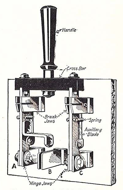
Diagram of a single-pole switch (Source: Wikimedia Commons)
- Two-Way Switches: Allow control of a circuit from two different locations, useful in long corridors or staircases in schools.
- Intermediate Switches: Used in three or more switch circuits to control a device from multiple points.
- Push-Button Switches: Momentary switches for doorbells or control panels.
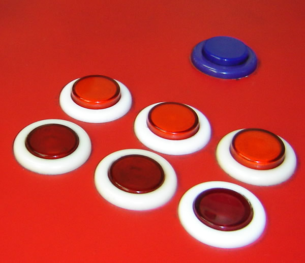
Various colored push-button switches on panel (Source: Wikipedia (Push-button))
- Rotary and Dimmer Switches: Provide variable control over lighting intensity, enhancing ambiance in hotels or restaurants.
Installation Guidelines for Switches
- Correct Positioning: Switches should be installed at convenient heights and locations for user accessibility.
- Secure Connections: Tight terminal screws and proper wiring prevent loose contacts and faults.
- Use of Suitable Switch Types: Selection depends on circuit requirements and user needs.
- Compliance with Wiring Colour Codes: Ensures safety and ease of maintenance.
- Provision of Adequate Insulation: Prevents accidental contact and electrical shock.
Troubleshooting and Maintenance
- Identifying Faulty Switches: Symptoms include flickering lights, failure to operate, or overheating.
- Replacing Worn Contacts: Over time, switch contacts degrade and require replacement to maintain functionality.
- Cleaning Switch Mechanisms: Dust and corrosion can impair operation.
- Testing Continuity: Using a tester to confirm switch operation during maintenance.
- Ensuring Safety During Repairs: Power must be isolated before any switch servicing.
3.1.4 Socket outlets
Socket outlets provide connection points for electrical appliances, enabling flexible and safe power distribution in various professional settings. In county hospitals and universities, properly installed socket outlets ensure reliable operation of medical equipment and computers.
Role and Importance of Socket Outlets
-
Power Access Points: Socket outlets allow users to plug in appliances without direct wiring.
-
Facilitating Equipment Mobility: Devices can be connected and disconnected easily, supporting dynamic work environments.
-
Safety Barrier: Outlets are designed to prevent accidental contact with live parts.
-
Standardized Interface: Ensures compatibility with plugs of different appliances.
- Supporting Load Distribution: Multiple outlets prevent overloading of single points, reducing fire risk.
Types of Socket Outlets
-
Single Socket Outlets: Provide one connection point, common in offices and classrooms.
-
Double Socket Outlets: Allow two appliances to be connected simultaneously, increasing convenience.
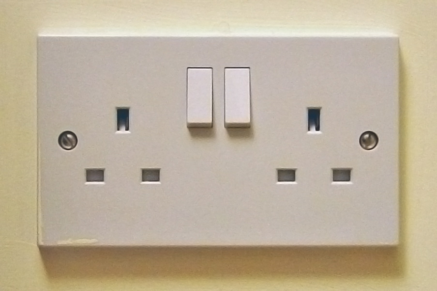
double socket outlet with switches (Source: Wikimedia Commons)
- Switched Socket Outlets: Include a switch to isolate power, enhancing safety.
- Weatherproof Socket Outlets: Designed for outdoor or wet environments, such as farms or construction sites.
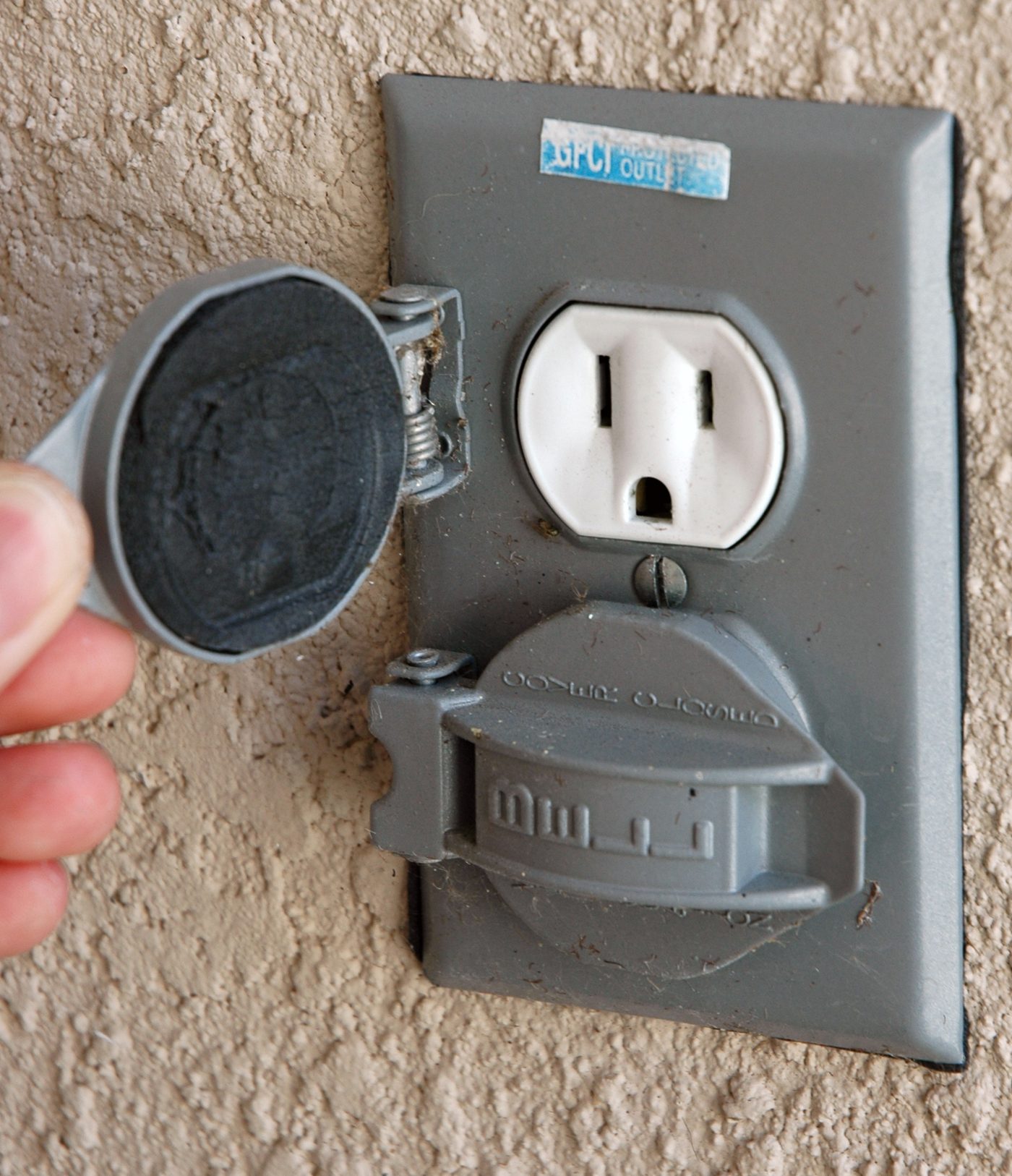
Outdoor weatherproof electrical socket outlet (Source: Wikimedia Commons)
- USB Integrated Socket Outlets: Provide additional charging ports for electronic devices, useful in hotels and modern offices.
Installation Requirements for Socket Outlets
- Appropriate Height and Location: Sockets must be accessible but away from water sources or heat.
- Correct Wiring and Earthing: Ensures safe operation and compliance with Kenyan electrical codes.
- Use of Quality Materials: High-grade sockets resist wear and reduce fire risk.
- Secure Mounting: Prevents movement that could loosen connections.
- Testing After Installation: Verifying polarity, insulation, and earth continuity is mandatory.
Maintenance and Safety Practices
- Regular Inspection for Damage: Cracked or loose sockets pose shock and fire hazards.
- Cleaning Dust and Debris: Keeps contacts free from obstruction and corrosion.
- Replacing Faulty Sockets Promptly: Prevents accidental electrocution or appliance damage.
- Avoiding Overloading: Using appropriate socket ratings prevents overheating.
- Educating Users: Proper use of sockets reduces misuse and accidents.
3.1.5 Bulb holders
Bulb holders provide the mechanical and electrical connection for light bulbs, enabling secure installation and easy replacement. In retail business premises, selecting the correct bulb holder type ensures lighting reliability and efficiency.
Functions of Bulb Holders
- Electrical Connection: Provide terminals for the bulb’s live and neutral contacts.
- Mechanical Support: Hold bulbs firmly to prevent loosening or falling.
- Heat Resistance: Materials used withstand heat generated by bulbs.
- Compatibility with Bulb Types: Different holders accommodate various bulb bases and wattages.
- Safety Features: Insulation and design prevent accidental contact with live parts.
Types of Bulb Holders
-
Bayonet Cap Holders: Common in Kenya, these holders use a twist-and-lock mechanism for secure fitting.
-
Screw Cap Holders: Used with Edison screw bulbs, offering simple installation.
-
Pin Base Holders: Designed for fluorescent or LED tube lights.
- Pendant Holders: Suspended holders for ceiling lighting.
- Recessed Holders: Installed within ceilings for flush lighting fixtures.
Installation Procedures for Bulb Holders
- Isolate Power Supply: Ensure the circuit is de-energized before installation.
- Select Appropriate Holder: Match holder type to bulb specifications and installation location.
- Mount Holder Securely: Fix to ceiling or wall ensuring mechanical stability.
- Connect Wiring Correctly: Attach live and neutral wires to designated terminals using insulated connectors.
- Check Polarity and Continuity: Verify correct connections to prevent faults.
- Fit Bulb and Test: Insert bulb and restore power to confirm proper operation.
Maintenance and Replacement
- Inspect for Signs of Wear: Cracks, discoloration, or loose fittings require prompt replacement.
- Clean Contacts: Remove dust to maintain good electrical contact.
- Replace Burnt-out Bulbs Safely: Always isolate power before changing bulbs.
- Check for Overheating: Excessive heat can damage holders and wiring.
- Upgrade to Energy-efficient Holders: Consider holders compatible with LED bulbs for energy savings.
Practice Questions
- Explain the role of junction boxes in electrical installations and list five considerations when installing them. (10 marks)
- Describe the different types of ceiling roses and their applications in commercial buildings. (10 marks)
- Discuss the functions of switches in electrical circuits and identify four types commonly used in offices. (10 marks)
- Outline the installation requirements for socket outlets in a county hospital setting. (10 marks)
- Detail the installation steps for bulb holders and explain why correct wiring is essential. (10 marks)
The rest of this chapter
🔒Create a free account to open more of this chapter.
Free: practical guides, quick cards, workplace scenarios and more.
Create a free account 🔒3.2 Component Symbols
In electrical installations, component symbols are essential for clear communication and accurate interpretation of electrical diagrams. These symbols represent various electrical components in circuit drawings, enabling technicians and engineers to understand…
🔒3.3 Safety in Electrical Installation
Safety is paramount in all electrical installation activities to prevent accidents, injuries, and damage to property. In Kenya, workplaces such as hospitals, schools, banks, and agricultural facilities must adhere to strict safety protocols to protect workers…
Chapter Summary
This chapter provided an in-depth exploration of essential electrical components used in installations, including junction boxes, ceiling roses, switches, socket outlets, and bulb holders, each described with their functional roles and installation considerations. It then introduced the standardized symbols representing these components on electrical diagrams, enabling accurate interpretation and communication during planning and execution. Emphasis was placed on safety measures critical to electrical installation work, highlighting precautions to prevent accidents and ensure compliance with regulatory standards. By understanding the characteristics and correct mounting of each component, learners gain the foundation necessary for safe and effective electrical installations. The chapter also reinforced the importance of interpreting component symbols correctly to avoid errors during wiring and assembly. Overall, the content equips students with both the practical knowledge of component handling and the theoretical skills to read and apply electrical schematics safely.
Self-Assessment
🔒 PDFDownload this self-assessment, with answers
A. Written Assessment
- Identify the primary function of a junction box in an electrical installation. (2 marks)
- List three types of switches commonly used in residential electrical wiring. (3 marks)
🔒20 more in this section.
Chapter Examination Questions
🔒 PDFDownload these examination questions, with worked answers
SECTION A (40 Marks) - Answer ALL Questions
- Explain the function of a junction box in an electrical installation at a county referral hospital and why proper mounting is essential. (4 marks)
- Describe the purpose of a ceiling rose and how it contributes to electrical safety in a university lecture hall. (4 marks)
🔒18 more in this section.
Chapter Practical Activities
Practical 1: Mount a 150mm x 150mm x 75mm Junction Box on Wall Surface
Electronics Engineering · Level 6
Electrical Installation I
PRACTICAL ASSESSMENT
TIME: 4 HOURS
⬇ PDFCandidate Instructions (Candidate Tool)
Type: Individual
INSTRUCTIONS TO CANDIDATE:
1. You are required to perform the following task:
i. Mount one 150mm x 150mm x 75mm PVC junction box on a wall surface ensuring level and secure fixing.
2. You have been provided with the following resources for the practical task:
| Tools & Equipment | Materials |
|---|
| Screwdriver | 150mm x 150mm x 75mm PVC Junction Box |
| Hammer Drill | 2.5 mm2 PVC Single Core Cable |
| Spirit Level | Screws 25mm |
| Tape Measure | Rawl Plugs 8mm |
| Pencil | Cable Clips 6mm |
| Wire Stripper | PVC Insulation Tape |
| Pliers | |
⬇ PDFResources Required (Cutting List)
| S/N | Item | Quantity |
|---|
| 1 | 150mm x 150mm x 75mm PVC Junction Box | 1 Pc per Candidate |
| 2 | 2.5 mm2 PVC Single Core Cable | 2.0 m per Candidate |
| 3 | Screws 25mm | 4 Pcs per Candidate |
| 4 | Rawl Plugs 8mm | 4 Pcs per Candidate |
| 5 | Cable Clips 6mm | 6 Pcs per Candidate |
| 6 | PVC Insulation Tape | 1 Roll per 5 Candidates |
| 7 | Wall Surface (as per site) | 1 per Candidate |
⬇ PDFAssessor Guide
| Items to be Evaluated | Marks Available | Marks Obtained | Comments |
|---|
| TASK 1: Mounting the Junction Box |
Wore Personal Protective Equipment (PPE) before starting work
(Award 1 mark for wearing PPE correctly, zero if not) | 1 | | |
Ensured the working area was clean and safe before commencing work
(Award 1 mark for good housekeeping practice) | 1 | | |
Measured and marked correct position for junction box on wall using tape measure and pencil
(Award 2 marks for accurate measurement and marking) | 2 | | |
Drilled holes accurately using hammer drill for rawl plugs
(Award 2 marks for correct drilling technique and hole placement) | 2 | | |
Inserted rawl plugs firmly into drilled holes
(Award 1 mark for correct rawl plug installation) | 1 | | |
Fixed junction box securely to wall using screws and screwdriver
(Award 3 marks for solid and secure fixing without movement) | 3 | | |
Used spirit level to ensure junction box is level in both horizontal and vertical planes
(Award 2 marks for proper levelling) | 2 | | |
Fixed cable clips uniformly to secure cables leading to junction box
(Award 2 marks for neat and evenly spaced cable clips) | 2 | | |
Stripped cable ends correctly without nicking and prepared cables for connection
(Award 2 marks for proper cable preparation) | 2 | | |
Applied PVC insulation tape neatly on cable joints if applicable
(Award 1 mark for neat insulation) | 1 | | |
Maintained good workmanship and neatness throughout the task
(Award 1 mark for overall neatness and professionalism) | 1 | | |
| Sub-Total | 18 | | |
| PRODUCT CHECKLIST |
Junction box fixed securely and level on wall surface (150mm x 150mm x 75mm) as per drawing
(Award 5 marks if box is firmly fixed and level within ±2mm tolerance) | 5 | | |
Cable clips spaced uniformly approximately 150mm apart and cables secured properly
(Award 3 marks for uniform clip spacing and cable securement) | 3 | | |
Cable ends stripped correctly with no damage and cables ready for wiring
(Award 3 marks for correct cable preparation and no conductor damage) | 3 | | |
| Sub-Total | 11 | | |
| GRAND TOTAL | 29 | | |
ASSESSMENT OUTCOME: ☐ Competent ☐ Not Yet Competent (competent if at least 50%)
Practical 2: Installation of a Ceiling Rose 100mm Diameter on Ceiling
Electronics Engineering · Level 6
Electrical Installation I
PRACTICAL ASSESSMENT
TIME: 4 HOURS
⬇ PDFCandidate Instructions (Candidate Tool)
Type: Individual
INSTRUCTIONS TO CANDIDATE:
1. You are required to perform the following task:
i. Mount a ceiling rose 100mm diameter on a ceiling board 300mm x 300mm and prepare it for wiring connections.
2. You have been provided with the following resources for the practical task:
| Tools & Equipment | Materials |
|---|
| Screwdriver | Ceiling rose 100mm diameter |
| Wire stripper | 1.5 mm2 PVC single core cable |
| Pliers | 2.5 mm2 PVC single core cable |
| Hammer | Cable clips |
| Tape measure | Screws and wall plugs |
| Spirit level | Insulation tape |
| Flat wooden mounting board 300mm x 300mm |
| Shallow Patrice box |
⬇ PDFResources Required (Cutting List)
| S/N | Item | Quantity |
|---|
| 1 | Ceiling rose 100mm diameter | 1 Pc per Candidate |
| 2 | 1.5 mm2 PVC single core cable | 3.0 M per Candidate |
| 3 | 2.5 mm2 PVC single core cable | 1.5 M per Candidate |
| 4 | Cable clips | 20 Pcs per Candidate |
| 5 | Screws and wall plugs | 6 Pcs per Candidate |
| 6 | Insulation tape | 1 Roll per 5 Candidates |
| 7 | Flat wooden mounting board 300mm x 300mm | 1 Pc per Candidate |
| 8 | Shallow Patrice box | 1 Pc per Candidate |
⬇ PDFAssessor Guide
| Items to be Evaluated | Marks Available | Marks Obtained | Comments |
|---|
| TASK 1: Mounting and Preparation of Ceiling Rose |
Wore Personal Protective Equipment (PPE)
(Award 1 mark for correct PPE use, else 0) | 1 | | |
Applied good housekeeping practice ensuring clean working area
(Award 1 mark for tidy workspace before starting) | 1 | | |
Used correct tools for mounting and cable preparation
(Award 1 mark for each correct tool used appropriately) | 2 | | |
Measured and marked mounting board accurately to 300mm x 300mm
(Award 2 marks for correct measurement and marking) | 2 | | |
Fixed flat wooden mounting board plumb and level on ceiling
(Award 3 marks for secure, level, and plumb fixing) | 3 | | |
Installed shallow Patrice box on mounting board securely
(Award 2 marks for proper fixing and alignment) | 2 | | |
Mounted ceiling rose securely on Patrice box
(Award 3 marks for correct and firm fixing of ceiling rose) | 3 | | |
Prepared cable ends correctly (stripped without damage, proper length)
(Award 2 marks for neat and correct cable preparation) | 2 | | |
Applied cable clips uniformly and spaced at 300mm intervals on cables
(Award 2 marks for neat, uniform cable fixing) | 2 | | |
Ensured correct colour coding of cables (live, neutral, earth)
(Award 2 marks for adherence to colour code) | 2 | | |
Prepared ceiling rose for wiring connections correctly
(Award 2 marks for correct terminal preparation and positioning) | 2 | | |
| Sub-Total | 22 | | |
| PRODUCT CHECKLIST |
Ceiling rose mounted centrally on 300mm x 300mm board, fixed plumb and level
(Award 5 marks for accurate positioning and firm fixing) | 5 | | |
Cables fixed neatly with clips spaced 300mm apart and colour coded
(Award 4 marks for neatness and correct cable management) | 4 | | |
Cable ends prepared and ready for wiring connections without damage
(Award 4 marks for neat and proper cable preparation) | 4 | | |
Shallow Patrice box fixed correctly to mounting board
(Award 3 marks for secure and aligned fixing) | 3 | | |
Overall workmanship, clean and safe installation
(Award 5 marks for professional finish and safety) | 5 | | |
| Sub-Total | 21 | | |
| GRAND TOTAL | 43 | | |
ASSESSMENT OUTCOME: ☐ Competent ☐ Not Yet Competent (competent if at least 50%)
🔒Mounting Electrical Switches on Wall BoxPractical 3
🔒Installation of double socket outlets on wall surfacePractical 4
🔒Mounting of Bulb Holders on Wall SurfacePractical 5
🔒Identify and explain standard electrical component symbols from a schematicPractical 6
🔒Safe Handling and Mounting of Electrical Components on a Distribution BoardPractical 7
🔒Combined mounting of a 1-gang switch and 13A socket outlet on a mounting boardPractical 8
🔒Setting Out Electrical Component Positions on Wall SurfacePractical 9
🔒Mounting multiple electrical components in a distribution boxPractical 10
