
By the end of this chapter, you will be able to:
Mastering these skills helps you keep complex systems running safely and efficiently, making you a valuable and confident member of any technical team.
Opto-electronics is a vital branch of electronics engineering that deals with devices capable of converting electrical signals into light and vice versa. In Kenya, the application of opto-electronic devices spans telecommunications, medical instrumentation, industrial automation, and consumer electronics. Understanding these devices equips electronics engineers with the skills to design and maintain systems that rely on light-based signal transmission and sensing, such as fibre optic networks and optical sensors used in manufacturing plants. This chapter focuses on the fundamental opto-electronic components, their operation principles, and practical applications in professional settings.
Light Emitting Diodes (LEDs) are semiconductor devices that emit light when an electric current passes through them. They are widely used in indicator lights, displays, and increasingly in lighting solutions due to their energy efficiency and long life span.
The operation of an LED is based on electroluminescence, where electrons recombine with holes within the semiconductor material, releasing energy in the form of photons (light). The colour of the emitted light depends on the semiconductor material and the energy band gap. For example, gallium arsenide (GaAs) produces infrared light, while gallium nitride (GaN) emits blue or ultraviolet light.
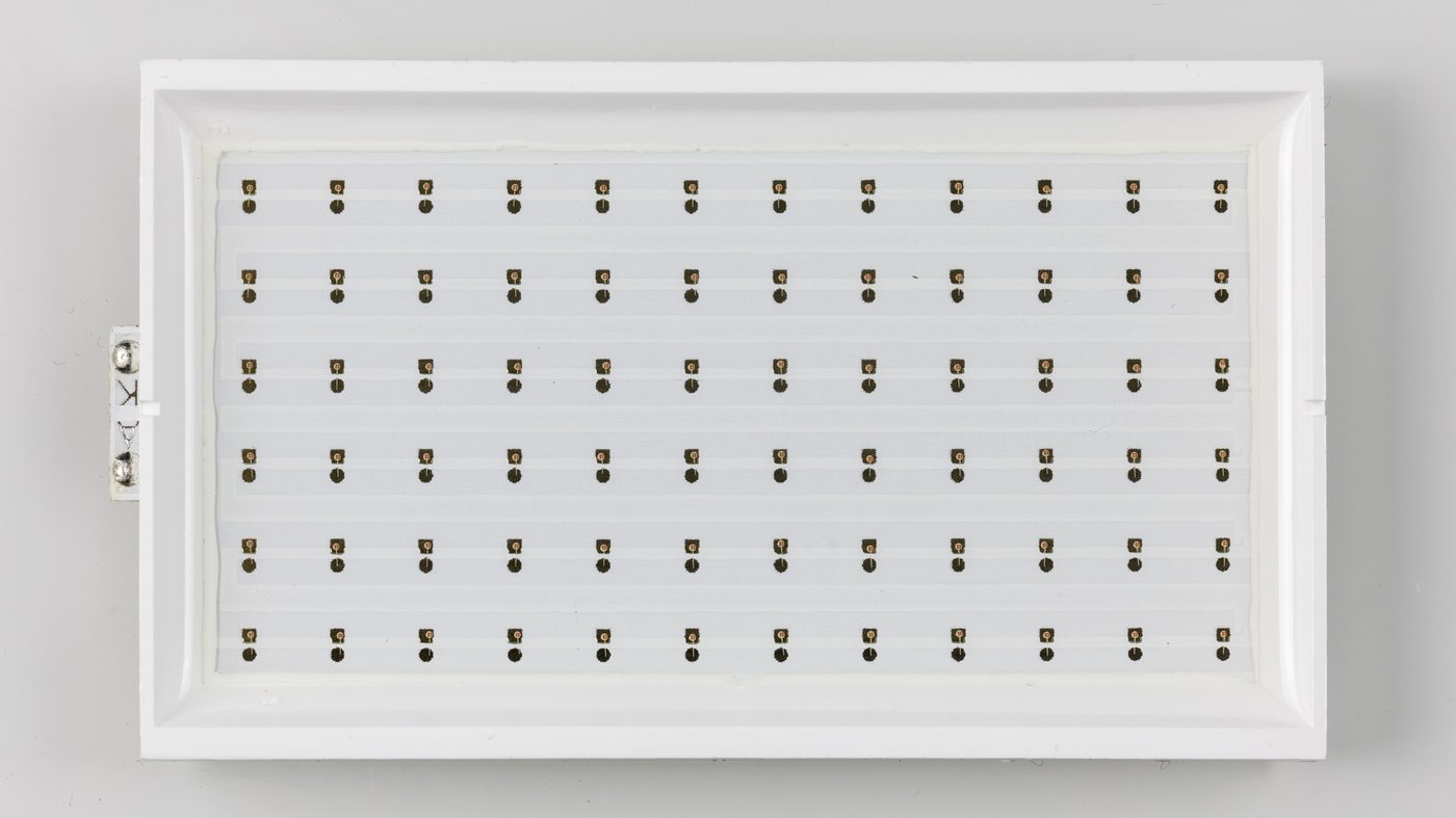
Rectangular panel with multiple display LEDs (Source: Wikimedia Commons)
High-Power LEDs: Used for illumination in street lighting systems managed by county governments.
Infrared LEDs: Utilized in remote controls and optical communication.
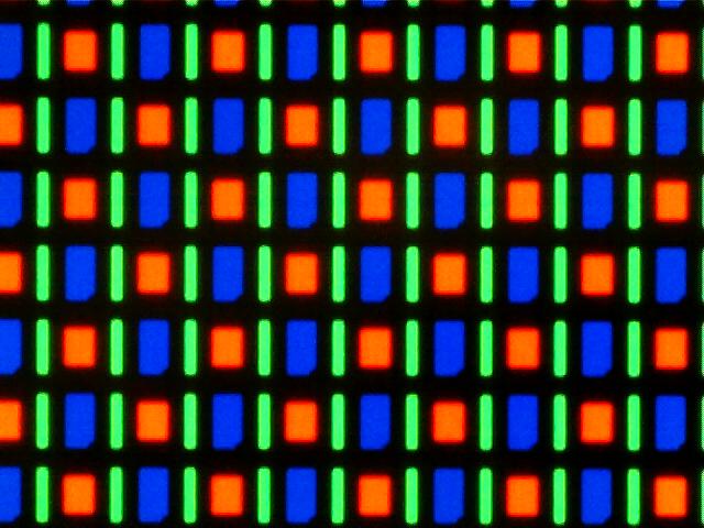
Close-up of organic LED pixel array (Source: Wikimedia Commons)
Organic Light Emitting Diodes (OLEDs) are composed of organic semiconductor layers that emit light when electrically stimulated. They are prominent in display technology due to their ability to produce bright, flexible, and thin screens.
OLEDs consist of multiple organic layers sandwiched between an anode and cathode. When voltage is applied, electrons and holes recombine in the emissive layer, producing light. The organic materials allow for flexible substrates, enabling curved or bendable displays.
Laser diodes generate coherent light through stimulated emission, differing fundamentally from LEDs by producing a highly focused, monochromatic beam. They are essential in fibre optic communication, barcode scanners, and laser printing.
Laser diodes operate on the principle of population inversion and optical feedback within a resonant cavity. When forward biased, electrons and holes recombine emitting photons which stimulate further emission, amplifying light in a coherent beam.
Photo transistors are light-sensitive transistors that amplify current generated by incident light. They are widely used in light sensing applications where signal amplification is necessary.
A photo transistor operates similarly to a regular transistor but uses light to generate base current instead of an electrical signal. When light strikes the base region, it creates electron-hole pairs that modulate the collector current, amplifying the detected light signal.
Photo diodes are semiconductor devices that convert light into current or voltage. They are preferred for fast, precise light detection in communication and measurement systems.
Photo diodes operate in reverse bias; incident photons generate electron-hole pairs in the depletion region, producing a photocurrent proportional to the light intensity. This current is then measured or amplified in the circuit.
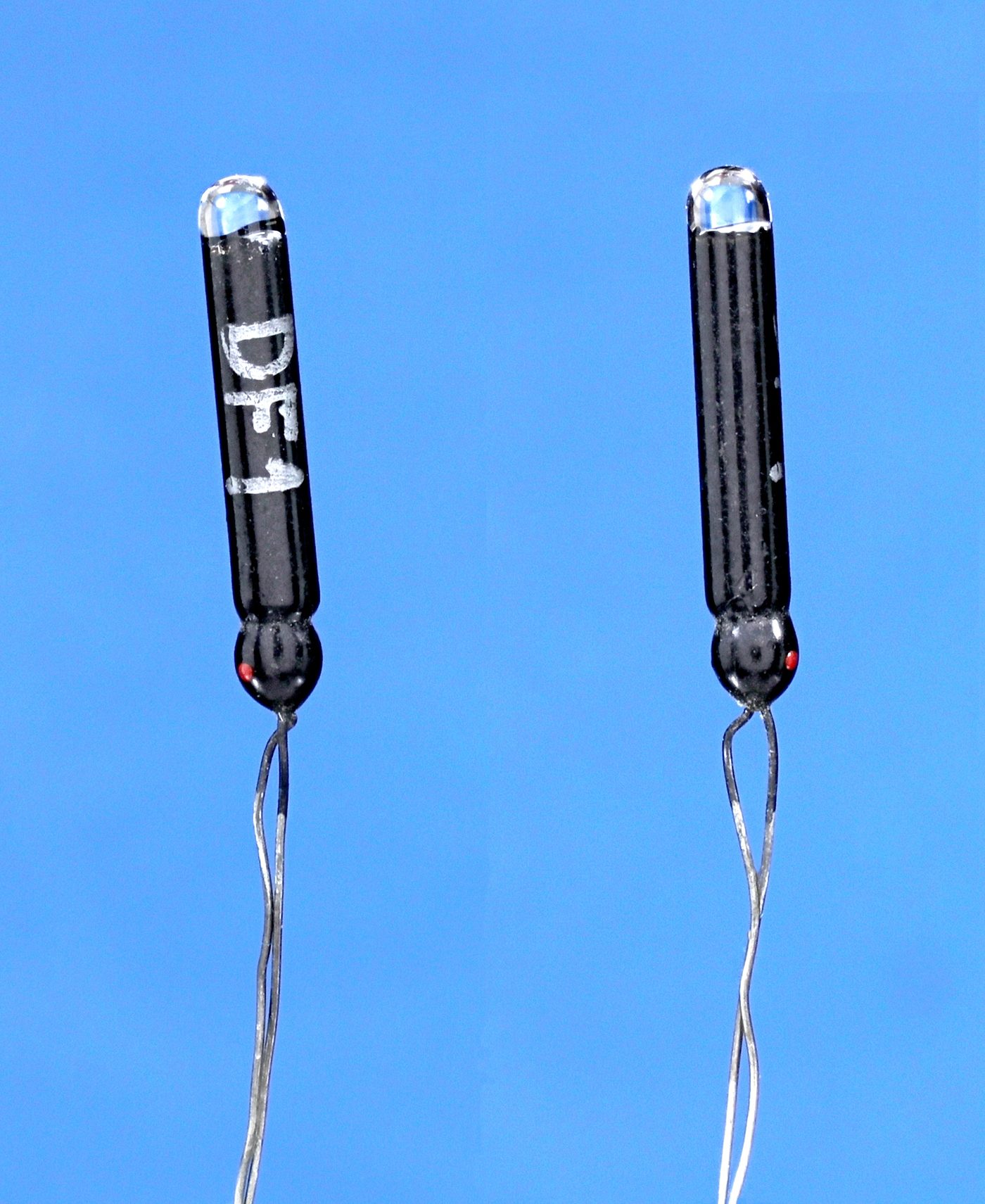
Two pn junction photodiodes DF-1 type (Source: Wikimedia Commons)
An optocoupler, or opto-isolator, is a device that transfers electrical signals using light to provide electrical isolation between input and output. This isolation is critical in protecting sensitive circuits in industrial and medical equipment.
An optocoupler typically combines an LED and a photodetector (photodiode or phototransistor) in a single package. When the LED is energized, it emits light detected by the photodetector, which then produces a corresponding electrical signal, thus transferring information without direct electrical connection.
Switching Power Supplies: Used in feedback loops to maintain voltage regulation.
Medical Devices: Ensuring patient safety by isolating electrical parts.
Light Activated Silicon Controlled Rectifier (LASCR) is a semiconductor device that switches on when exposed to light, combining features of SCRs and photodetectors. It is used in power control and switching applications where optical triggering is advantageous.
LASCRs remain in a non-conductive state until illuminated by light of sufficient intensity. Photons generate carriers that trigger the device into conduction, allowing control of large currents with an optical signal instead of electrical gate triggering.
Light-Activated Relays: Providing contactless switching in hazardous environments.
Motor Control: Enabling remote switching in automated systems.
Create a free account to open more of this chapter.
Free: practical guides, quick cards, workplace scenarios and more.
Create a free accountThis chapter explored various opto-electronic devices, beginning with Light Emitting Diodes (LEDs), which convert electrical signals into light, followed by Organic LEDs (OLEDs) that offer flexible and efficient display options. The chapter then discussed LASER diodes, known for their coherent light emission used in communication and sensing. Photo transistors and photo diodes were examined as light-sensitive components that detect and convert light into electrical signals. The optocoupler was introduced as a device that transfers electrical signals using light to provide electrical isolation. LASCR devices, specialized semiconductor components, were also covered for their role in controlling high power through light activation. Moving to display technologies, Liquid Crystal Displays (LCDs) were detailed with their dynamic scattering and field effect scattering types, highlighting how liquid crystals manipulate light for visual output. The chapter concluded with an overview of LASERs and MASERs, emphasizing their applications in communication and measurement, and summarized the broad range of practical uses for opto-electronics across various industries.
Type: Individual
| Tools & Equipment | Materials |
|---|---|
| Digital Multimeter (with diode test function) | Red LED 5mm |
| Variable DC Power Supply 0-12V | Green LED 5mm |
| Connecting Wires (jumper wires) | Blue LED 5mm |
| Resistors 330Ω 1/4 Watt | |
| Breadboard 830 tie points | |
| Multimeter Test Leads | |
| Personal Protective Equipment (Safety boots, Dust coat) |
| S/N | Item | Quantity |
|---|---|---|
| 1 | Red LED 5mm | 2 pcs per Candidate |
| 2 | Green LED 5mm | 2 pcs per Candidate |
| 3 | Blue LED 5mm | 2 pcs per Candidate |
| 4 | Digital Multimeter (with diode test function) | 1 pc per Candidate |
| 5 | Variable DC Power Supply 0-12V | 1 pc per 2 Candidates |
| 6 | Resistors 330Ω 1/4 Watt | 4 pcs per Candidate |
| 7 | Connecting Wires (jumper wires) | 10 pcs per Candidate |
| 8 | Breadboard 830 tie points | 1 pc per Candidate |
| 9 | Personal Protective Equipment (Safety boots, Dust coat) | 1 set per Candidate |
| 10 | Multimeter Test Leads | 1 pair per Candidate |
| 11 | Work Table with good lighting | 1 per Candidate |
| Items to be Evaluated | Marks Available | Marks Obtained | Comments |
|---|---|---|---|
| TASK 1: Preparation and PPE | |||
| Wore Personal Protective Equipment (Safety boots and Dust coat) (Award 1 mark if worn properly, 0 if not) | 1 | ||
| Ensured working area was clean and well-arranged before starting (Award 1 mark if clean and organized, 0 if not) | 1 | ||
| Sub-Total | 2 | ||
| TASK 2: Component Identification and Setup | |||
| Correctly identified Red, Green, and Blue LEDs (Award 2 marks if all identified correctly, 1 if partially correct, 0 if wrong) | 2 | ||
| Mounted LEDs on the breadboard with correct polarity (Award 2 marks if all LEDs mounted with correct polarity, 0 if any reversed) | 2 | ||
| Connected 330Ω resistors in series with each LED (Award 2 marks if all resistors correctly connected, 0 if missing or incorrect) | 2 | ||
| Wired the circuit to the variable DC power supply correctly (Award 3 marks if circuit wired without fault, 0 if incorrect wiring) | 3 | ||
| Sub-Total | 9 | ||
| TASK 3: Testing and Measurement | |||
| Used the multimeter diode test function to measure forward voltage of each LED (Award 3 marks if forward voltage measured correctly for all LEDs, 0 if not) | 3 | ||
| Powered the circuit using variable DC power supply set between 2V to 3.5V (Award 2 marks if correct voltage range used, 0 if outside range) | 2 | ||
| Observed and confirmed light emission from each LED when powered (Award 3 marks if all LEDs emit light correctly, 0 if any do not) | 3 | ||
| Sub-Total | 8 | ||
| TASK 4: Reporting and Cleanup | |||
| Recorded forward voltage values for Red, Green, and Blue LEDs accurately (Award 3 marks if all values recorded correctly, 0 if missing or wrong) | 3 | ||
| Disconnected all equipment safely and cleaned working area (Award 2 marks if area cleaned and equipment disconnected safely, 0 if not) | 2 | ||
| Sub-Total | 5 | ||
| PRODUCT CHECKLIST | |||
| Forward voltage measurements for Red LED within 1.8V to 2.2V (Award 2 marks if within range, 0 if not) | 2 | ||
| Forward voltage measurements for Green LED within 2.0V to 3.0V (Award 2 marks if within range, 0 if not) | 2 | ||
| Forward voltage measurements for Blue LED within 3.0V to 3.5V (Award 2 marks if within range, 0 if not) | 2 | ||
| LEDs emit visible light when powered (Award 3 marks if all LEDs emit light, 0 if any do not) | 3 | ||
| Circuit connections are neat and secure on breadboard (Award 2 marks if neat and firm, 0 if loose or messy) | 2 | ||
| Sub-Total | 11 | ||
| GRAND TOTAL | 35 | ||
Type: Individual
| Tools & Equipment | Materials |
|---|---|
| Digital multimeter | 128x64 OLED Display Module |
| Soldering iron and solder wire | Microcontroller (ATmega328P) on DIP socket |
| Side cutter | Resistors (10kΩ, 220Ω) |
| Oscilloscope | Capacitors (0.1µF ceramic) |
| Breadboard | 5V DC regulated power supply |
| Jumper wires | Personal Protective Equipment (Safety boots, dustcoat, gloves) |
| S/N | Item | Quantity |
|---|---|---|
| 1 | 128x64 OLED Display Module | 1 Pc per Candidate |
| 2 | Microcontroller (ATmega328P) on DIP socket | 1 Pc per Candidate |
| 3 | Resistors (10kΩ, 220Ω) | 2 Pcs per Candidate |
| 4 | Capacitors (0.1µF ceramic) | 1 Pc per Candidate |
| 5 | Breadboard (400 tie-points) | 1 Pc per Candidate |
| 6 | Jumper wires assorted colors | 20 Pcs per Candidate |
| 7 | 5V DC regulated power supply | 1 Pc per Candidate |
| 8 | Digital multimeter | 1 Pc per Candidate |
| 9 | Soldering iron and solder wire | 1 set per 2 Candidates |
| 10 | Side cutter | 1 Pc per Candidate |
| 11 | Personal Protective Equipment (Safety boots, dustcoat, gloves) | 1 set per Candidate |
| 12 | Oscilloscope | 1 Pc per 3 Candidates |
| Items to be Evaluated | Marks Available | Marks Obtained | Comments |
|---|---|---|---|
| TASK 1: Preparation and Safety | |||
| Wore Personal Protective Equipment (Safety boots, dustcoat, gloves) (Award 1 or 0) | 1 | ||
| Ensured clean and organized working area before starting assembly (Award 1 or 0) | 1 | ||
| Sub-Total | 2 | ||
| TASK 2: Component Identification and Mounting | |||
| Correctly identified all components and their values (Award 3 or 0) | 3 | ||
| Mounted microcontroller and components neatly on the breadboard (Award 3 or 0) | 3 | ||
| Used correct jumper wires to connect the OLED display as per schematic (Award 2 or 0) | 2 | ||
| Sub-Total | 8 | ||
| TASK 3: Wiring, Soldering and Circuit Completion | |||
| Performed neat soldering with shiny, smooth joints where applicable (Award 4 or 0) | 4 | ||
| Trimmed excess wire leads neatly after soldering (Award 1 or 0) | 1 | ||
| Connected power supply and ensured correct polarity (Award 2 or 0) | 2 | ||
| Sub-Total | 7 | ||
| TASK 4: Testing and Verification | |||
| Used digital multimeter to check continuity and correct voltage at key points (Award 3 or 0) | 3 | ||
| Used oscilloscope to verify signal integrity on data lines (Award 3 or 0) | 3 | ||
| Demonstrated correct operation by controlling display segments as per instructions (Award 5 or 0) | 5 | ||
| Sub-Total | 11 | ||
| TASK 5: Housekeeping and Documentation | |||
| Cleaned working area and stored tools and materials properly (Award 1 or 0) | 1 | ||
| Submitted a brief test report documenting measurements and observations (Award 3 or 0) | 3 | ||
| Sub-Total | 4 | ||
| PRODUCT CHECKLIST | |||
| Circuit assembled as per schematic with neat wiring and secure connections (Award 5 or 0) | 5 | ||
| OLED display module mounted firmly and aligned within approx. 100mm x 70mm area (Award 3 or 0) | 3 | ||
| Display segments respond correctly to control signals during testing (Award 7 or 0) | 7 | ||
| Sub-Total | 15 | ||
| GRAND TOTAL | 47 | ||
At the start of this chapter we promised you would be able to:
Tick each one you can genuinely do.
So, are you there yet?
You're competent when you can confidently do 50% or more of what this chapter promised.
Sign in to record how you're doing.