
By the end of this chapter, you will be able to:
Mastering these skills helps you keep electrical systems running safely and efficiently, which is essential for reliable and safe operations in the trade.
Rectification is a fundamental process in analogue electronics that converts alternating current (AC) into direct current (DC), enabling the operation of virtually all electronic devices and systems that require steady DC voltage. In Kenya's growing electronics industry, from manufacturing to service sectors, understanding rectifiers is critical for designing and maintaining power supplies in equipment such as hospital diagnostic machines, banking servers, and telecommunications infrastructure. This chapter explores the types of rectifiers used in practical electronics engineering, focusing on half wave and full wave rectifiers, which form the backbone of power conversion circuits.
Rectifiers are electronic circuits designed to convert AC voltage into DC voltage. The choice of rectifier type affects output quality, efficiency, and complexity. In Kenyan electronics workshops and industries, selecting the appropriate rectifier ensures reliable operation of devices ranging from small consumer electronics to industrial machinery. This section explains the two primary categories of rectifiers: half wave and full wave, highlighting their configurations and operational principles.
Half wave rectifiers are the simplest form of rectification, allowing current to pass through during only one half of the AC cycle. They are widely used in low-power applications where cost and simplicity are critical, such as in small power supplies for radios or basic instrumentation in educational laboratories.
The half wave rectifier operates by permitting current flow only during the positive half-cycle of the input AC voltage. A single diode is connected in series with the load resistor. During the positive half-cycle, the diode is forward biased and conducts current, delivering voltage to the load. During the negative half-cycle, the diode is reverse biased, effectively blocking current flow and resulting in zero voltage across the load.
The main components include:
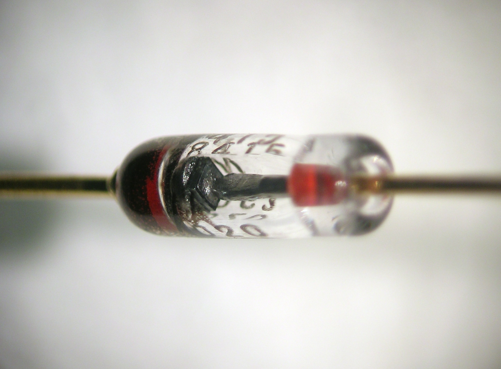
Close-up of a glass diode component (Source: Wikimedia Commons)
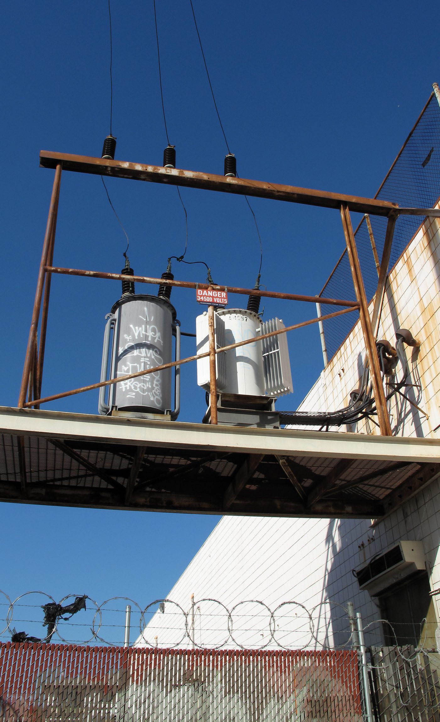
Outdoor electrical transformers on a pole (Source: Wikimedia Commons)
Filter Capacitor (optional): Smooths the pulsating DC output to reduce voltage ripple.
Input AC Source: Provides the alternating voltage to be rectified.
Half wave rectifiers have several advantages:
However, they also have significant limitations:
In Kenya, half wave rectifiers are commonly found in:
Full wave rectifiers improve upon half wave designs by utilizing both halves of the AC input, producing a higher average output voltage with lower ripple. This makes them essential in power supplies for professional electronics equipment, including hospital diagnostic machines and banking data centers in Kenya.
A center-tap full wave rectifier uses a transformer with a center-tapped secondary winding and two diodes. The center tap acts as a common ground reference. During the positive half-cycle, one diode conducts current through the load, while the other blocks. During the negative half-cycle, roles reverse, and the second diode conducts. This arrangement allows current flow through the load in the same direction during both half cycles, effectively doubling the frequency of the output waveform compared to a half wave rectifier.
The bridge rectifier employs four diodes arranged in a bridge circuit, eliminating the need for a center-tapped transformer. During each half-cycle of the AC input, two diodes conduct to direct current through the load in the same direction. This design is more economical when transformers with center taps are unavailable or costly. The bridge rectifier is favored in Kenyan electronics workshops for its compactness and efficiency.
| Feature | Center-Tap Rectifier | Bridge Rectifier |
|---|---|---|
| Transformer Requirement | Requires center-tapped transformer | Uses standard transformer |
| Number of Diodes | Two | Four |
| Output Voltage | Approximately half of secondary voltage | Approximately full secondary voltage |
| Circuit Complexity | Moderate | Slightly higher due to more diodes |
| Efficiency | High | Slightly higher due to full waveform utilization |
Full wave rectifiers offer multiple benefits:
Create a free account to open more of this chapter.
Free: practical guides, quick cards, workplace scenarios and more.
Create a free accountThis chapter explored the fundamental concepts and types of rectifiers, beginning with half wave and full wave rectifiers, including center-tap and bridge configurations. It then examined the various classes of rectifiers such as uncontrolled, controlled, half-controlled, and fully-controlled types, highlighting their distinct operational characteristics. The practical applications of rectifiers were discussed, emphasizing their role in converting alternating current to direct current in different electronic devices. The chapter also covered the different types of converters, detailing AC to DC converters, DC to AC inverters, DC to DC converters, and AC to AC converters, explaining their functions and distinctions. Finally, the applications of these converters were reviewed, illustrating their importance in power electronics and energy management systems. This comprehensive overview provides a solid foundation for understanding rectification and conversion processes in analogue electronics.
Type: Individual
| Tools & Equipment | Materials |
|---|---|
| Oscilloscope | Breadboard |
| Digital multimeter | Diode 1N4001 |
| Electronic toolkit | Resistor 1kΩ |
| Side cutter | Capacitor 470µF |
| Jumper wires | |
| 12V AC power supply | |
| Personal Protective Equipment |
| S/N | Item | Quantity |
|---|---|---|
| 1 | Breadboard | 1 Pc per Candidate |
| 2 | Diode 1N4001 | 2 Pcs per Candidate |
| 3 | Resistor 1kΩ | 1 Pc per Candidate |
| 4 | Capacitor 470µF, 25V electrolytic | 1 Pc per Candidate |
| 5 | Jumper wires | Enough per Candidate |
| 6 | Oscilloscope | 1 Pc per 2 Candidates |
| 7 | 12V AC power supply (transformer output) | 1 Pc per Candidate |
| 8 | Digital multimeter | 1 Pc per Candidate |
| 9 | Electronic toolkit (pliers, wire stripper, screwdriver) | 1 set per Candidate |
| 10 | Personal Protective Equipment (safety boots, dust coat) | 1 set per Candidate |
| 11 | Side cutter | 1 Pc per Candidate |
| Items to be Evaluated | Marks Available | Marks Obtained | Comments |
|---|---|---|---|
| TASK 1: Preparation and safety | |||
| Wore Personal Protective Equipment (safety boots and dust coat) (Award 1 or 0) | 1 | ||
| Observed good housekeeping practices (clean working area before starting) (Award 1 or 0) | 1 | ||
| Sub-Total | 2 | ||
| TASK 2: Circuit assembly on breadboard | |||
| Identified and used correct components (1N4001 diode, 1kΩ resistor, 470µF capacitor) (Award 1 mark each for correct component identification) | 3 | ||
| Connected components on breadboard according to half wave rectifier schematic (Award 4 or 0) | 4 | ||
| Used jumper wires neatly and correctly (Award 2 or 0) | 2 | ||
| Connected 12V AC power supply correctly without short circuits (Award 2 or 0) | 2 | ||
| Sub-Total | 11 | ||
| TASK 3: Testing and measurement | |||
| Performed general inspection and correct setup of oscilloscope before use (Award 2 or 0) | 2 | ||
| Connected oscilloscope probe and ground clip correctly to circuit output (Award 2 or 0) | 2 | ||
| Displayed and observed half wave rectified output waveform on oscilloscope (Award 3 or 0) | 3 | ||
| Measured output voltage using digital multimeter at correct test points (Award 3 or 0) | 3 | ||
| Determined frequency of output waveform using oscilloscope time base and calculations (Award 3 or 0) | 3 | ||
| Sub-Total | 13 | ||
| PRODUCT CHECKLIST | |||
| Half wave rectifier circuit output waveform observed on oscilloscope with correct shape (positive half cycles only) (Award 5 or 0) | 5 | ||
| Measured output voltage approximately 9V DC after rectification (±0.5V tolerance) (Award 3 or 0) | 3 | ||
| Circuit assembled neatly and firmly on breadboard with correct component placement (Award 4 or 0) | 4 | ||
| Sub-Total | 12 | ||
| GRAND TOTAL | 38 | ||
Type: Individual
| Tools & Equipment | Materials |
|---|---|
| Digital Multimeter | Step-down Transformer 12V center-tap |
| Oscilloscope | Diodes 1N4001 |
| Soldering gun | Capacitor 470uF 25V electrolytic |
| Side cutter | Capacitors 0.1uF ceramic |
| Jumper wires | Breadboard 9cm x 6cm |
| S/N | Item | Quantity |
|---|---|---|
| 1 | Step-down Transformer 12V center-tap | 1 Pc per Candidate |
| 2 | Diodes 1N4001 | 4 Pcs per Candidate |
| 3 | Capacitor 470uF 25V electrolytic | 1 Pc per Candidate |
| 4 | Capacitors 0.1uF ceramic | 2 Pcs per Candidate |
| 5 | Breadboard 9cm x 6cm | 1 Pc per Candidate |
| 6 | Jumper wires | Enough per Candidate |
| 7 | Digital Multimeter | 1 Pc per 2 Candidates |
| 8 | Oscilloscope | 1 Pc per 3 Candidates |
| 9 | Soldering gun | 1 Pc per Candidate |
| 10 | Soldering wire | Enough per Candidate |
| 11 | Side cutter | 1 Pc per Candidate |
| 12 | Personal Protective Equipment (Safety boots, Dustcoat) | Appropriate per Candidate |
| 13 | Working table | Enough per Candidate |
| Items to be Evaluated | Marks Available | Marks Obtained | Comments |
|---|---|---|---|
| TASK 1: Preparation and Safety | |||
| Wore Personal Protective Equipment (Safety boots, Dustcoat) (Award 2 marks or 0) | 2 | ||
| Observed good housekeeping practices (clean working area before starting) (Award 1 mark or 0) | 1 | ||
| Sub-Total | 3 | ||
| TASK 2: Circuit Assembly | |||
| Identified and selected correct components as per schematic (Award 3 marks or 0) | 3 | ||
| Mounted the transformer and diodes properly on the breadboard (Award 1 mark each for correct placement of transformer and 3 diodes) | 4 | ||
| Connected the center tap correctly as per circuit schematic (Award 2 marks or 0) | 2 | ||
| Connected capacitors correctly for filtering (Award 3 marks or 0) | 3 | ||
| Used jumper wires neatly and correctly (Award 2 marks or 0) | 2 | ||
| Sub-Total | 14 | ||
| TASK 3: Testing and Measurement | |||
| Powered the circuit using the 12V center-tap transformer (Award 2 marks or 0) | 2 | ||
| Measured DC output voltage correctly at the output terminals (Award 3 marks or 0) | 3 | ||
| Measured ripple voltage using oscilloscope correctly (Award 4 marks or 0) | 4 | ||
| Recorded all measurements accurately (Award 2 marks or 0) | 2 | ||
| Sub-Total | 11 | ||
| TASK 4: Cleanup and Reporting | |||
| Turned off power supply and disconnected circuit safely (Award 1 mark or 0) | 1 | ||
| Organized tools and disposed of waste materials properly (Award 1 mark or 0) | 1 | ||
| Sub-Total | 2 | ||
| PRODUCT CHECKLIST | |||
| Finished circuit on breadboard is neat, components firmly fixed and correctly wired (Award 5 marks or 0) | 5 | ||
| Measured DC output voltage within expected range 15V ±0.5V (Award 4 marks or 0) | 4 | ||
| Ripple voltage measured is less than 1V peak-to-peak (Award 4 marks or 0) | 4 | ||
| Circuit dimensions on breadboard are approximately 90mm length x 60mm width (Award 2 marks or 0) | 2 | ||
| Sub-Total | 15 | ||
| GRAND TOTAL | 45 | ||
At the start of this chapter we promised you would be able to:
Tick each one you can genuinely do.
So, are you there yet?
You're competent when you can confidently do 50% or more of what this chapter promised.
Sign in to record how you're doing.