Electronics Engineering  ·  Level 5
Power Supply Systems II
Chapter 2: Assemble Power Supply Prototypes
📚 5 Topics
⚑ What you will be able to do

By the end of this chapter, you will be able to:

  • Wear the correct personal protective equipment safely and confidently, following your company’s safety policies.
  • Evaluate the operation and electrical design of power supply equipment accurately using the manufacturer’s instructions.
  • Understand and apply company, master’s, and chief engineer’s standing orders to maintain safety and compliance.
  • Assess current engine room and machinery conditions correctly by following company operating procedures.
  • Follow the ship’s Safety Management System to observe all electrical safety rules, industry standards, and company guidelines.
  • Monitor the parameters on the Main Switchboard, Emergency Switchboard, and Distribution boards correctly and safely.
  • Record the electrical parameters accurately according to company procedures.
  • Report the parameters clearly and professionally to the relevant team members.
  • Respond promptly and correctly by reporting accidents, incidents, and near misses as required by the Safety Management System.

Mastering these skills will help you work safely and effectively in real power supply environments, keeping yourself and others protected while ensuring smooth operations.

Power supply prototypes form the foundation for developing reliable electronic systems in Kenya's growing electronics industry. Electronics engineers must assemble these prototypes with precision, using suitable components and adhering to strict safety and quality standards. This chapter explores the critical processes involved in assembling power supply prototypes, emphasizing the professional practices and technical skills required to meet industry expectations in Kenyan manufacturing and repair workshops.

2.1 Component Assembly Supply

Component assembly supply involves the systematic procurement, handling, and preparation of electronic components to ensure they are fit for integration into power supply prototypes. In Kenya’s electronics workshops, managing component assembly supply effectively reduces errors, prevents damage, and maintains the integrity of the final product.

2.1.1 Safety Protocols: Prototypes

Safety protocols are essential during prototype assembly to protect both personnel and components from harm. In Kenyan electronics labs and production units, adherence to safety measures prevents accidents and ensures equipment longevity.

Personal Protective Equipment (PPE) Requirements

  • Eye Protection: Safety goggles shield eyes from solder splashes and flying debris during assembly.
  • Gloves: Anti-static gloves prevent electrostatic discharge damage and protect hands from burns.

Pair of yellow work gloves used in carpentry
Pair of yellow work gloves used in carpentry (Source: Wikimedia Commons)
  • Proper Clothing: Wearing long sleeves and non-flammable fabric reduces injury risk from hot soldering irons.
  • Ventilation Masks: Masks prevent inhalation of solder fumes which contain harmful substances like lead and flux.
  • Footwear: Closed-toe shoes protect feet from falling tools or components in workshop environments.

Electrical Safety Measures

  • Power Isolation: Ensure power supplies are disconnected before assembly or testing to avoid electric shock.
  • Use of Insulated Tools: Tools with insulated handles prevent accidental short circuits and shocks.
  • Safe Work Surfaces: Non-conductive mats and grounded workbenches reduce risk of static discharge.
  • Emergency Procedures: Knowledge of first aid and fire protocols is mandatory for rapid response to accidents.
  • Testing Equipment Calibration: Using properly calibrated multimeters and oscilloscopes prevents inaccurate readings that could cause unsafe conditions.

Workspace Organization and Cleanliness

  • Component Storage: Organized storage prevents mix-ups and damage to sensitive parts.
  • Clear Work Areas: Free of clutter to avoid accidental damage or component loss.
  • Proper Disposal: Safe disposal of solder waste and electronic scrap reduces environmental hazards.
  • Labeling: Clear labeling of components and subassemblies improves assembly accuracy.
  • Routine Cleaning: Regular cleaning of soldering stations and tools maintains functionality and safety.

Handling of Hazardous Materials

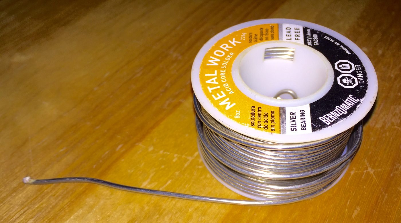
  • Lead-Based Solder: Awareness of lead toxicity and use of lead-free alternatives where possible.

Spool of lead-based solder wire
Spool of lead-based solder wire (Source: Wikipedia (Solder))

  • Flux Fumes: Use of fume extractors to minimize inhalation of harmful vapors.
  • Chemical Storage: Proper storage of cleaning solvents and flux removers in labeled, ventilated areas.
  • Spill Management: Procedures to contain and clean chemical spills promptly.
  • Training: Regular staff training on handling and emergency response for hazardous substances.

2.1.2 Use of Grounded Workstations and Wrist Straps (ANSI/ESD S20.20)

Electrostatic discharge (ESD) poses a significant risk to sensitive electronic components during assembly. Grounded workstations and wrist straps following ANSI/ESD S20.20 standards are essential in Kenyan electronics workshops to prevent component failure.

Principles of Electrostatic Discharge Control

ESD control involves regulating the transfer of static electricity from personnel or equipment to electronic parts. Static charges can destroy semiconductors and integrated circuits used in power supplies, leading to prototype failure.

Grounded Workstation Setup

  • Conductive Mats: Work surfaces made of conductive material dissipate static charges safely.

  • Grounding Points: Connection to earth ground ensures static electricity flows away from components.

  • Equipment Grounding: Tools and equipment must be electrically bonded to the workstation ground.
  • Regular Testing: Resistance and continuity of grounding systems should be verified routinely.
  • Clear Signage: Workstations should display ESD warning signs to remind workers of precautions.

Wrist Strap Usage and Maintenance

  • Proper Wearing: Wrist straps must maintain skin contact to provide a path for static discharge.
  • Ground Connection: The strap’s cord should connect securely to the workstation ground.
  • Daily Testing: Wrist straps require daily inspection with a tester to ensure functionality.
  • Cord Care: Avoid stretching or tangling cords which can break internal wiring.
  • Replacement: Defective or worn straps must be replaced immediately to maintain protection.

Personnel Training and Compliance

  • Awareness Programs: Regular training on ESD risks and control measures improves compliance.
  • Standard Operating Procedures: Clear guidelines on when and how to use grounding equipment.
  • Monitoring: Supervisors should observe and enforce proper ESD practices during assembly.
  • Incident Reporting: Any ESD events must be documented and analyzed to prevent recurrence.
  • Continuous Improvement: Feedback from staff is used to enhance ESD control protocols.

2.1.3 Handling guidelines for moisture-sensitive components (IPC/JEDEC J-STD-033)

Moisture-sensitive devices (MSDs) are vulnerable to damage from humidity, which can cause soldering defects such as popcorn cracking. Kenyan electronics engineers must follow IPC/JEDEC J-STD-033 guidelines to preserve component integrity.

Identification and Classification of Moisture-Sensitive Components

  • Component Markings: MSDs are marked with moisture sensitivity level (MSL) labels indicating allowable floor life.
  • Common MSD Types: Includes plastic encapsulated ICs, BGAs, and certain capacitors.
  • Moisture Absorption Risks: Humidity penetrates packaging, causing internal delamination during reflow.
  • Sensitivity Levels: MSL ranges from 1 (no sensitivity) to 6 (high sensitivity with short exposure limits).
  • Storage Conditions: Proper storage environments prevent moisture uptake before assembly.

Packaging and Storage Requirements

  • Moisture Barrier Bags: Components must be stored in sealed bags with desiccants and humidity indicators.
  • Controlled Environments: Use of dry cabinets or nitrogen-purged storage for highly sensitive parts.
  • Humidity Monitoring: Regular checks of relative humidity inside storage units ensure compliance.
  • Shelf Life Tracking: Date codes and floor life timers monitor allowable exposure periods.
  • Re-Sealing Procedures: Bags must be properly resealed after inspection or partial use.

Pre-Assembly Baking Procedures

  • Purpose of Baking: Removes absorbed moisture to prevent damage during solder reflow.
  • Temperature and Duration: Typical baking at 125°C for 8 to 24 hours, depending on component type.
  • Equipment Used: Use of convection ovens or specialized baking chambers with precise temperature control.
  • Handling After Baking: Components must be promptly used or returned to dry storage to avoid re-absorption.
  • Documentation: Baking logs maintained for traceability and quality assurance.

Handling During Assembly

  • Minimizing Exposure: Components removed from packaging only when ready for immediate use.
  • Use of Humidity Indicator Cards: Monitor ambient moisture levels at the workstation.
  • Floor Life Management: Track elapsed time from opening to soldering to prevent exceeding MSL limits.
  • Re-baking if Necessary: Components exposed beyond allowable floor life must be baked again before use.
  • Training Staff: Personnel educated on the importance of moisture control to avoid latent defects.

2.1.4 Soldering Techniques

Soldering is a critical skill in assembling power supply prototypes, determining the mechanical and electrical integrity of connections. Kenyan electronics technicians must master various soldering techniques to achieve high-quality results.

Types of Soldering Methods

  • Hand Soldering: Using soldering irons for manual assembly of through-hole and surface mount components.
  • Reflow Soldering: Controlled heating in ovens to melt solder paste for surface mount devices.
  • Wave Soldering: Automated process for soldering multiple through-hole components simultaneously.
  • Selective Soldering: Precision soldering of specific joints on mixed-technology boards.
  • Laser Soldering: High-precision technique for miniature or delicate assemblies.

Preparation for Soldering

  • Component and PCB Cleaning: Ensures surfaces are free from oxidation and contaminants for good wetting.
  • Solder Paste Application: Even and appropriate quantity applied for surface mount assembly.
  • Tool Selection: Choosing the right soldering iron tip size and temperature for the components.
  • Flux Usage: Proper flux type enhances solder flow and prevents oxidation.
  • Workstation Setup: Adequate lighting, ventilation, and ergonomic arrangement improve quality and safety.

Hand Soldering Technique

  • Temperature Control: Maintain soldering iron between 300°C and 350°C to avoid overheating components.
  • Tip Contact: Heat both the pad and lead simultaneously to ensure proper solder flow.
  • Solder Application: Feed solder wire to the heated joint, allowing it to flow evenly without excess.
  • Joint Inspection: Look for smooth, shiny, and concave fillets indicating good solder joints.
  • Cleaning: Remove flux residues with appropriate solvents to avoid corrosion.
  • Practice: Regular skill development improves speed and consistency.

Quality Assurance of Solder Joints

  • Visual Inspection: Identifies cold joints, bridges, or insufficient solder.
  • Mechanical Testing: Gentle tug tests ensure joint strength without damaging components.
  • Electrical Testing: Continuity and resistance measurements verify proper connectivity.
  • Rework Procedures: Defective joints must be reheated and resoldered following best practices.
  • Documentation: Recording inspection results supports traceability and process improvement.

Practice Questions

  1. Explain five key safety protocols that must be observed when assembling power supply prototypes in a Kenyan electronics workshop. (10 marks)

  2. Describe the importance of using grounded workstations and wrist straps according to ANSI/ESD S20.20 in electronic component assembly. (8 marks)

  3. Outline the handling guidelines for moisture-sensitive components based on IPC/JEDEC J-STD-033 standards, including storage and pre-assembly procedures. (12 marks)

  4. Compare and contrast hand soldering and reflow soldering techniques, highlighting their applications in power supply prototype assembly. (10 marks)

The rest of this chapter
🔒

Create a free account to open more of this chapter.

Free: practical guides, quick cards, workplace scenarios and more.

Create a free account
🔒2.2 Input/Output Testing

Input/output testing is a critical stage in assembling power supply prototypes, ensuring that the device performs as intended under real-world electrical conditions. In the Kenyan electronics engineering sector, where reliable power conversion is essential for…

🔒2.3 Stability Diagnostics

In the design and assembly of power supply prototypes, ensuring stability is critical to reliable operation and safety. For electronics engineers in Kenya, who often work on sensitive equipment in hospitals, universities, and manufacturing plants, instability…

🔒2.4 EMI Mitigation

In electronics engineering, especially within Kenya’s growing technology sector, managing Electromagnetic Interference (EMI) is critical for ensuring the reliability and safety of power supply systems. EMI can degrade system performance and cause malfunctions…

🔒2.5 Compliance Validation

Compliance validation is a critical phase in assembling power supply prototypes, ensuring that the design adheres to international safety and electromagnetic compatibility standards. For electronics engineers in Kenya, especially those working in design and ma…

Chapter Summary

This chapter examined the assembly of power supply prototypes, beginning with essential safety protocols to protect both the components and the technician. It emphasized the importance of grounded workstations and wrist straps following ANSI/ESD S20.20 standards, as well as proper handling of moisture-sensitive components according to IPC/JEDEC J-STD-033. Soldering techniques were covered to ensure reliable connections. The chapter then addressed input/output testing, focusing on IEC 61000-4-11 compliance through voltage dip and surge immunity tests, alongside performance evaluations including load regulation and efficiency measurements. Stability diagnostics were explored through loop stability testing with network analyzers, detection of parasitic oscillations, and appropriate oscilloscope and spectrum analyzer methods. EMI mitigation strategies were detailed, highlighting conducted and radiated EMI assessments, LISN measurements, filter designs, near-field probing, and shielding validation. Finally, the chapter concluded with compliance validation procedures involving safety standards IEC/EN 62368, creepage and clearance measurements, fault condition testing, and EMC requirements such as CISPR 32 radiated emissions and harmonic current emissions under IEC 61000-3-2.

Self-Assessment

🔒 PDFDownload this self-assessment, with answers

A. Written Assessment

  1. What is the primary purpose of using grounded workstations and wrist straps according to ANSI/ESD S20.20? (2 marks)
  2. Describe the key handling precautions for moisture-sensitive components as per IPC/JEDEC J-STD-033. (3 marks)
🔒20 more in this section.

Chapter Examination Questions

🔒 PDFDownload these examination questions, with worked answers

SECTION A (40 Marks) - Answer ALL Questions

  1. Explain the importance of using grounded workstations and wrist straps when assembling power supply prototypes in a Kenyan electronics workshop. (4 marks)
  2. Describe the key safety protocols that must be observed when working with power supply prototypes to prevent electrical hazards. (4 marks)
🔒18 more in this section.

Chapter Practical Activities

Practical 1: Assemble a Power Supply Prototype on a 60mm x 50mm Stripboard with ESD and Moisture Sensitive Component Handling

Electronics Engineering · Level 5
Power Supply Systems II
PRACTICAL ASSESSMENT
TIME: 4 HOURS
⬇ PDFCandidate Instructions (Candidate Tool)

Type: Individual

INSTRUCTIONS TO CANDIDATE:
1.  You are required to perform the following task:
i.  Assemble and solder a power supply prototype on a 60mm x 50mm stripboard following ESD and moisture-sensitive component handling protocols.
2.  You have been provided with the following resources for the practical task:
Tools & EquipmentMaterials
Long Nose PliersCopper Stripboard (60mm x 50mm)
Soldering GunStep-down Transformer 9V AC
Side CutterDiodes (1N4001)
TweezerCapacitor 470uF Electrolytic
Digital MultimeterCapacitors 0.1uF Ceramic
OscilloscopeVoltage Regulator 7805
Electronics ToolkitJumper Wires Insulated
Personal Protective Equipment (ESD Wrist Strap, Grounded Workstation Mat, Dustcoat)Moisture Barrier Bags for Sensitive Components
⬇ PDFResources Required (Cutting List)
S/NItemQuantity
1Copper Stripboard (60mm x 50mm)1 Pc per Candidate
2Step-down Transformer 9V AC1 Pc per Candidate
3Diodes (1N4001)4 Pcs per Candidate
4Capacitor 470uF Electrolytic1 Pc per Candidate
5Capacitors 0.1uF Ceramic2 Pcs per Candidate
6Voltage Regulator 78051 Pc per Candidate
7Jumper Wires InsulatedEnough per Candidate
8Long Nose Pliers1 Pc per Candidate
9Soldering Gun1 Pc per Candidate
10Soldering WireEnough per Candidate
11Side Cutter1 Pc per Candidate
12Tweezer1 Pc per Candidate
13Digital Multimeter1 Pc per Candidate
14Electronics Toolkit1 Pc per Candidate
15Oscilloscope1 Pc per Candidate
16Personal Protective Equipment (ESD Wrist Strap, Grounded Workstation Mat, Dustcoat)Appropriate per Candidate
17Moisture Barrier Bags for Sensitive Components1 Bag per 3 Candidates
⬇ PDFAssessor Guide
Items to be EvaluatedMarks AvailableMarks ObtainedComments
TASK 1: Safety and Preparation
Wore Personal Protective Equipment including ESD wrist strap and dustcoat
(Award 2 marks or 0)
2
Applied good housekeeping practice by ensuring clean and organized workstation
(Award 1 mark or 0)
1
Correctly handled moisture-sensitive components by storing and unpacking from moisture barrier bags
(Award 2 marks or 0)
2
Used grounded workstation mat and wrist strap correctly during assembly
(Award 2 marks or 0)
2
Sub-Total7
TASK 2: Component Assembly and Soldering
Identified and placed all components correctly on the stripboard according to schematic
(Award 1 mark each for all 6 component types correctly placed)
6
Fixed components firmly and neatly on the stripboard
(Award 8 marks or 0)
8
Soldered joints are shiny, smooth, and free from lumps or bridges
(Award 9 marks or 0)
9
Trimmed component leads and ensured jumper wires are properly insulated
(Award 3 marks or 0)
3
Sub-Total26
TASK 3: Testing and Verification
Powered the circuit safely with 9V AC step-down transformer
(Award 2 marks or 0)
2
Measured output voltages at test points within ±0.5V of expected values
(Award 3 marks or 0)
3
Used oscilloscope to verify waveform shape at output
(Award 3 marks or 0)
3
Sub-Total8
PRODUCT CHECKLIST
Prototype assembly matches the 60mm x 50mm stripboard dimensions with neat and uniform component spacing
(Award 2 marks or 0)
2
All components correctly connected as per schematic with no visible faults
(Award 3 marks or 0)
3
Solder joints inspected for firmness and quality with no cold joints or shorts
(Award 3 marks or 0)
3
Sub-Total8
GRAND TOTAL49
ASSESSMENT OUTCOME:   ☐ Competent    ☐ Not Yet Competent (competent if at least 50%)

Practical 2: Solder a power supply prototype on a 60mm x 50mm copper stripboard

Electronics Engineering · Level 5
Power Supply Systems II
PRACTICAL ASSESSMENT
TIME: 4 HOURS
⬇ PDFCandidate Instructions (Candidate Tool)

Type: Individual

INSTRUCTIONS TO CANDIDATE:
1.  You are required to perform the following task:
i.  Solder a power supply prototype on a 60mm x 50mm copper stripboard.
2.  You have been provided with the following resources for the practical task:
Tools & EquipmentMaterials
Long Nose Pliers240V AC Power Source
Soldering gunStep-down Transformer 9V AC power supply
Side cutterDiodes (1N4001)
TweezerCapacitor (470uF)
Digital multimeterCapacitors (0.1uF)
OscilloscopeVoltage regulator 7805
Electronics tool kitJumper wires
Copper Strip board (60mm x 50mm)
Soldering wire
Personal Protective Equipment
⬇ PDFResources Required (Cutting List)
S/NItemQuantity
1240V AC Power Source1 Pc per Candidate
2Step-down Transformer 9V AC power supply1 Pc per Candidate
3Diodes (1N4001)4 Pcs per Candidate
4Capacitor (470uF)1 Pc per Candidate
5Capacitors (0.1uF)2 Pcs per Candidate
6Voltage regulator 78051 Pc per Candidate
7Jumper wiresEnough per Candidate
8Long Nose Pliers1 Pc per Candidate
9Copper Strip board (60mm x 50mm)1 Pc per Candidate
10Soldering gun1 Pc per Candidate
11Soldering wireEnough per Candidate
12Side cutter1 Pc per Candidate
13Tweezer1 Pc per Candidate
14Digital multimeter1 Pc per Candidate
15Electronics tool kit1 Pc per Candidate
16Oscilloscope1 Pc per Candidate
17Personal Protective Equipment (dustcoat, safety boots, gloves)Appropriate per Candidate
18Working tableEnough per Candidate
⬇ PDFAssessor Guide
Items to be EvaluatedMarks AvailableMarks ObtainedComments
TASK 1: Preparation and Safety
Wore Personal Protective Equipment including dustcoat and safety boots
(Award 2 or 0)
2
Applied good housekeeping practice by ensuring a clean working area before starting
(Award 2 or 0)
2
Identified and correctly used tools and equipment
(Award 3 or 0)
3
Sub-Total7
TASK 2: Component Mounting and Soldering
Mounted diodes correctly on the copper stripboard
(Award 1 mark each for 4 diodes or 0)
4
Mounted capacitors (470uF and 0.1uF) correctly
(Award 1 mark each for 3 capacitors or 0)
3
Mounted voltage regulator 7805 correctly
(Award 2 or 0)
2
Fixed components firmly and neatly
(Award 1 mark each for 8 components or 0)
8
Soldered joints are shiny, smooth, clean with concave fillet; no lumps
(Award 1 mark for each well-made joint or 0)
9
Jumper wires are properly insulated and correctly connected
(Award 1 mark each for 3 correctly insulated jumpers or 0)
3
Trimmed long terminals neatly
(Award 2 or 0)
2
Ensured economy of the stripboard with efficient component placement
(Award 2 or 0)
2
Observed neatness throughout the assembly
(Award 2 or 0)
2
Sub-Total35
TASK 3: Testing and Verification
Powered the circuit with correct input voltage (9V AC from transformer)
(Award 3 or 0)
3
Measured voltage at test points using digital multimeter: TP1 = 12 ± 0.5V, TP2 = 5 ± 0.5V
(Award 2 marks each for correct voltage or 0)
4
Used oscilloscope to observe and draw waveform at output test point
(Award 4 or 0)
4
Performed continuity test and verified correct polarity of components
(Award 3 or 0)
3
Sub-Total14
PRODUCT CHECKLIST
Finished soldered power supply prototype on copper stripboard 60mm x 50mm meets schematic requirements
(Award 5 or 0)
5
Component spacing is uniform and components are correctly oriented
(Award 3 or 0)
3
Solder joints are of high quality: shiny, smooth, clean, concave fillet
(Award 6 or 0)
6
No short circuits or cold joints present
(Award 5 or 0)
5
Trimmed leads are neat and do not interfere with other components
(Award 2 or 0)
2
Measured voltages at test points match expected values: TP1 = 12V ± 0.5V, TP2 = 5V ± 0.5V
(Award 4 or 0)
4
Waveform observed at output matches expected DC voltage (flat line) on oscilloscope
(Award 4 or 0)
4
Sub-Total29
GRAND TOTAL85
ASSESSMENT OUTCOME:   ☐ Competent    ☐ Not Yet Competent (competent if at least 50%)
🔒

Free: practical guides, quick cards, workplace scenarios and more.

Create a free account
🔒Input and Output Functional Testing of Power Supply PrototypePractical 3
🔒Voltage Dip/Sag and Surge Immunity Testing on Power Supply PrototypePractical 4
🔒Load Regulation and Efficiency Measurement of a Power Supply PrototypePractical 5
🔒Stability Diagnostics and Loop Stability Testing of a Power Supply PrototypePractical 6
🔒Parasitic Oscillation Identification in Power Supply PrototypePractical 7
🔒Demonstrate Correct Oscilloscope Probing TechniquesPractical 8
🔒Spectrum Analyzer Setup for Conducted Noise MeasurementPractical 9
🔒Conducted EMI Measurement on Power Supply Using LISN as per CISPR 32Practical 10
🔒Design and Implementation of EMI Filter Prototype with Common-Mode Chokes and X/Y CapacitorsPractical 11
🔒Radiated EMI Measurement and Near-field Probing on Power Supply PrototypePractical 12
🔒Shielding Effectiveness Validation of a Power Supply PrototypePractical 13
🔒Safety Compliance and Creepage/Clearance Measurement on Power Supply PrototypePractical 14
🔒Fault Condition Testing of a Power Supply PrototypePractical 15
🔒Conduct Radiated Emissions and Harmonic Current Emissions Testing for EMC CompliancePractical 16
Flashcards 20 cards Study deck ▾
Question
1

↻ Tap card to reveal answer
🔒

18 more in this section.

Create a free account
Test Yourself 20 questions Start quiz ▾
0%
0 / 2
🔒

18 more in this section.

Create a free account
Am I competent?

At the start of this chapter we promised you would be able to:

  • Wear the correct personal protective equipment safely and confidently, following your company’s safety policies.
  • Evaluate the operation and electrical design of power supply equipment accurately using the manufacturer’s instructions.
  • Understand and apply company, master’s, and chief engineer’s standing orders to maintain safety and compliance.
  • Assess current engine room and machinery conditions correctly by following company operating procedures.
  • Follow the ship’s Safety Management System to observe all electrical safety rules, industry standards, and company guidelines.
  • Monitor the parameters on the Main Switchboard, Emergency Switchboard, and Distribution boards correctly and safely.
  • Record the electrical parameters accurately according to company procedures.
  • Report the parameters clearly and professionally to the relevant team members.
  • Respond promptly and correctly by reporting accidents, incidents, and near misses as required by the Safety Management System.

Tick each one you can genuinely do.

So, are you there yet?

You're competent when you can confidently do 50% or more of what this chapter promised.

Sign in to record how you're doing.