Electronics Engineering  ·  Level 5
Technical Drawing
Chapter 6: Produce electrical drawings
📚 6 Topics
⚑ What you will be able to do

By the end of this chapter, you will be able to:

  • Accurately identify valves and pipe sizes from electrical drawings using technical drawing standards.
  • Correctly recognize types of fluids and their directional flow in diagrams according to technical standards and your work environment.
  • Understand and explain the sequence of operation for valves and machinery from drawings to meet workplace needs.
  • Identify which valves need to be isolated during both emergency and normal operations by following company procedures.
  • Follow assembly and disassembly steps for machinery based on workplace requirements and manufacturer instructions.
  • Accurately identify machinery components from drawings using technical standards and manufacturer manuals.
  • Interpret dimensions, instructions, and material requirements precisely according to technical drawing standards.

Mastering these skills will help you create and understand electrical drawings confidently, ensuring safe and efficient work in your trade.

Electrical drawings are foundational to the work of electronics engineers in Kenya, enabling clear communication of circuit designs, installation layouts, and system functions. These drawings must conform to established standards and use universally recognized symbols and abbreviations to avoid misinterpretation. Mastery of electrical symbols and understanding the meaning behind different types of electrical drawings are essential skills for professionals involved in design, maintenance, and troubleshooting of electronic systems in diverse sectors such as hospitals, universities, banks, and county government offices.

6.1 Electrical Symbols and Abbreviations

Electrical symbols and abbreviations form the language of electrical drawings. In the Kenyan electronics engineering context, these symbols ensure that electrical components and circuits are accurately represented and understood by technicians, engineers, and contractors. Standardization according to BS, ISO, and Kenya Bureau of Standards (KEBS) conventions guarantees consistency across projects and facilitates effective communication among multidisciplinary teams.

6.1.1 Standardization of Electrical Symbols

Electrical symbols must conform to recognized standards to maintain clarity and prevent errors during installation or maintenance.

  • British Standards (BS): BS 3939 and BS EN 60617 specify graphical symbols for electrical diagrams widely adopted in Kenya.
  • International Organization for Standardization (ISO): ISO 14617 provides a global set of symbols ensuring interoperability in multinational projects.
  • Kenya Bureau of Standards (KEBS): KEBS adopts and enforces standards aligning with BS and ISO for local compliance.
  • Consistency: Using standardized symbols prevents ambiguity and ensures uniform interpretation across different documents.
  • Updates: Engineers must stay current with revisions to standards to incorporate new symbols or retire obsolete ones.

6.1.2 Common Electrical Symbols Used in Electronics Engineering

A variety of symbols represent components and devices commonly encountered in electronics engineering drawings.

  • Resistor: Represented by a zigzag line or rectangle, indicating an element that resists current flow.

  • Capacitor: Two parallel lines with a gap, symbolizing energy storage in an electric field.
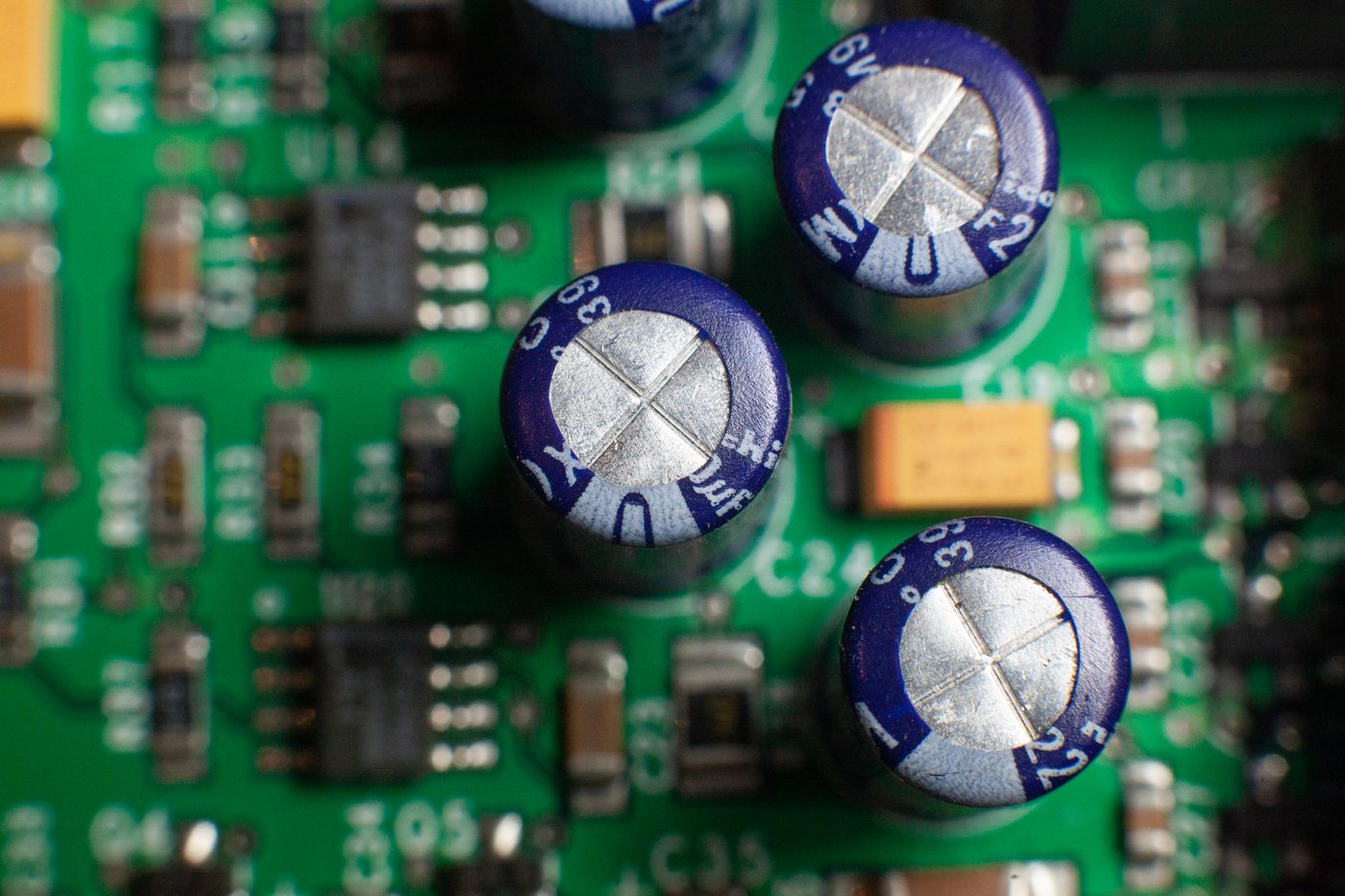
Electrolytic capacitors on a circuit board
Electrolytic capacitors on a circuit board (Source: Wikimedia Commons)

  • Diode: A triangle pointing to a line, indicating a component allowing current flow in one direction.

  • Ground: A set of three descending lines of decreasing length, representing the reference point for circuits.

  • Switch: Depicted as a break in a line with a pivot, showing a device controlling circuit continuity.

6.1.3 Electrical Abbreviations and Their Usage

Abbreviations condense complex terminology into concise labels, facilitating space-efficient and clear drawings.

  • V: Voltage, the potential difference measured in volts.
  • I: Current, the flow of electric charge in amperes.
  • Ω: Ohm, the unit of resistance.
  • AC/DC: Alternating current / Direct current, indicating the type of power source.
  • LED: Light Emitting Diode, a semiconductor device emitting light when energized.

6.1.4 Application of Symbols and Abbreviations in Circuit Diagrams

Applying these symbols and abbreviations correctly ensures that circuit diagrams convey precise information.

  • Component Identification: Symbols must be clearly labeled with abbreviations for easy recognition.
  • Circuit Connections: Lines representing conductors must be drawn with appropriate line types (solid for conductors, dashed for wiring not visible).
  • Polarity Indication: Symbols for polarized components, like electrolytic capacitors and diodes, must show correct orientation.
  • Annotation: Abbreviations are used alongside symbols to indicate values such as resistance (e.g., 1kΩ), voltage ratings, or current limits.
  • Layering: Complex diagrams may use different line weights or colors (where applicable) to distinguish between signal, power, and ground lines.

Practice Questions

  1. List and explain five British Standards relevant to electrical symbols in electronics engineering (10 marks)
  2. Draw and label electrical symbols for a resistor, capacitor, diode, ground, and switch (15 marks)
  3. Explain the significance of electrical abbreviations V, I, Ω, AC/DC, and LED in circuit diagrams (10 marks)
  4. Describe six key steps to correctly apply electrical symbols and abbreviations in a circuit diagram (15 marks)
The rest of this chapter
🔒

Create a free account to open more of this chapter.

Free: practical guides, quick cards, workplace scenarios and more.

Create a free account
🔒6.2 Meaning of Electrical Drawings

Electrical drawings are graphical representations that convey the details of electrical systems and circuits. In Kenya’s electronics engineering profession, these drawings guide the design, installation, testing, and maintenance of electronic equipment across…

🔒6.3 Drawing of electrical diagrams e.g. block, schematic, circuit, line and wiring

Electrical diagrams are vital communication tools for electronics engineers in Kenya, providing clear visual representation of electrical systems. These drawings ensure proper installation, troubleshooting, and maintenance of electronic equipment in diverse se…

🔒6.4 Drawing of Electrical and Electronic Drawings Using an Appropriate CAD Software

In Kenya’s dynamic electronics engineering sector, precision and efficiency in creating electrical and electronic drawings are crucial. Computer-Aided Design (CAD) software has transformed traditional drafting by enabling engineers to produce detailed, scalabl…

🔒6.5 Simulation of Electrical and Electronic Drawings

Simulation plays a vital role in validating electrical and electronic designs before physical implementation. In the Kenyan electronics industry, simulation reduces costly errors and accelerates development cycles in sectors like telecommunications, renewable…

🔒6.6 Installation of Electrical Components in a Building Plan Using AutoCAD

In Kenya's growing infrastructure and electronics sectors, precision and clarity in electrical installations are critical. Using AutoCAD to produce electrical component layouts in building plans ensures accuracy, compliance with national standards, and ease of…

Chapter Summary

This chapter introduces the fundamental electrical symbols and abbreviations essential for interpreting and producing electrical drawings accurately. It explains the purpose and significance of different types of electrical drawings in conveying detailed information about electrical systems. The chapter covers the step-by-step construction of various electrical diagrams including block, schematic, circuit, line, and wiring diagrams, highlighting their distinct uses and presentation standards. It further explores the use of appropriate CAD software for creating precise electrical and electronic drawings, emphasizing efficiency and accuracy. Simulation techniques for testing and validating electrical drawings are discussed to ensure functional reliability before implementation. Finally, the chapter details the process of installing electrical components within a building plan using AutoCAD, integrating design with practical application for effective electrical system planning.

Self-Assessment

🔒 PDFDownload this self-assessment, with answers

A. Written Assessment

  1. What is the standard symbol for a resistor in an electrical drawing according to BS standards? (2 marks)
  2. Explain the difference between a block diagram and a schematic diagram in electrical drawings. (4 marks)
🔒25 more in this section.

Chapter Examination Questions

🔒 PDFDownload these examination questions, with worked answers

SECTION A (40 Marks) - Answer ALL Questions

  1. Identify and explain the meaning of the following electrical symbols commonly used in electronics engineering drawings: resistor, capacitor, diode, and ground. (4 marks)
  2. Differentiate between a block diagram and a schematic diagram in the context of electronics circuit design. (4 marks)
🔒31 more in this section.

Chapter Practical Activities

Practical 1: Identify and Interpret Electrical Symbols and Abbreviations in Electrical Drawings

Electronics Engineering · Level 5
Technical Drawing
PRACTICAL ASSESSMENT
TIME: 4 HOURS
⬇ PDFCandidate Instructions (Candidate Tool)

Type: Individual

INSTRUCTIONS TO CANDIDATE:
1.  You are required to perform the following task:
i.  Identify and interpret standard electrical symbols and abbreviations on two A3 electrical wiring diagrams as per the provided reference chart.
2.  You have been provided with the following resources for the practical task:
Tools & EquipmentMaterials
Technical Drawing Set Square (45° and 60°)Electrical drawing sheets (A3 size)
Mechanical Pencil 0.5 mmElectrical Symbols and Abbreviations Reference Chart
Eraser
Ruler (30 cm)
Highlighter Pen
⬇ PDFResources Required (Cutting List)
S/NItemQuantity
1Electrical drawing sheets (A3 size)2 Sheets per Candidate
2Technical Drawing Set Square (45° and 60°)1 Set per Candidate
3Mechanical Pencil 0.5 mm2 Pcs per Candidate
4Eraser1 Pc per Candidate
5Ruler (30 cm)1 Pc per Candidate
6Electrical Symbols and Abbreviations Reference Chart1 Chart per Candidate
7Highlighter Pen1 Pc per Candidate
⬇ PDFAssessor Guide
Items to be EvaluatedMarks AvailableMarks ObtainedComments
TASK 1: Identification and Interpretation
Wore Personal Protective Equipment - safety boots
(Award 1 or 0)
1
Observed good housekeeping - clean working area before starting
(Award 1 or 0)
1
Used the reference chart correctly to identify electrical symbols
(Award 3 or 0)
3
Correctly matched symbols to their abbreviations on the drawings
(Award 5 or 0)
5
Accurately explained the meaning of at least 10 standard electrical symbols
(Award 1 mark each for 10 correct explanations, else 0)
10
Highlighted symbols and abbreviations neatly on the drawing sheets
(Award 2 or 0)
2
Sub-Total22
PRODUCT CHECKLIST
Electrical symbols on drawings correctly identified and highlighted
(Award 8 or 0)
8
Abbreviations correctly interpreted with matching symbols
(Award 10 or 0)
10
Clean and legible annotations on drawings with correct spelling
(Award 5 or 0)
5
All required symbols and abbreviations identified as per reference chart
(Award 5 or 0)
5
Drawings are free from smudges and erasure marks
(Award 3 or 0)
3
Sub-Total31
GRAND TOTAL53
ASSESSMENT OUTCOME:   ☐ Competent    ☐ Not Yet Competent (competent if at least 50%)

Practical 2: Draw a block electrical diagram for a single-phase lighting circuit

Electronics Engineering · Level 5
Technical Drawing
PRACTICAL ASSESSMENT
TIME: 4 HOURS
⬇ PDFCandidate Instructions (Candidate Tool)

Type: Individual

INSTRUCTIONS TO CANDIDATE:
1.  You are required to perform the following task:
i.  Draw a block electrical diagram of a single-phase lighting circuit showing main components on A3 paper with dimensions 420mm x 297mm as per the provided schematic.
2.  You have been provided with the following resources for the practical task:
Tools & EquipmentMaterials
HB PencilA3 Drawing Paper
Ruler 300mmElectrical Symbols Chart
Set Square (45°/60°)Personal Protective Equipment (Safety boots, Dustcoat)
Protractor
Eraser
⬇ PDFResources Required (Cutting List)
S/NItemQuantity
1A3 Drawing Paper1 Sheet per Candidate
2HB Pencil1 Pc per Candidate
3Eraser1 Pc per Candidate
4Ruler 300mm1 Pc per Candidate
5Set Square (45°/60°)1 Pc per Candidate
6Protractor1 Pc per Candidate
7Electrical Symbols Chart1 Chart per Candidate
8Personal Protective Equipment (Safety boots, Dustcoat)Appropriate per Candidate
⬇ PDFAssessor Guide
Items to be EvaluatedMarks AvailableMarks ObtainedComments
TASK 1: Drawing the block electrical diagram
Wore Personal Protective Equipment including safety boots and dustcoat
(Award 1 mark if PPE worn correctly, otherwise 0)
1
Ensured clean and organized working area before starting
(Award 1 mark for good housekeeping, otherwise 0)
1
Used correct drawing tools appropriately (ruler, set square, protractor, pencil)
(Award 1 mark each for correct use of measuring and drawing tools)
2
Accurately drew the block diagram showing main components: supply, switch, fuse, lamp, and wiring connections
(Award marks for correct symbols and arrangement: 1 mark each for supply, switch, fuse, lamp, and wiring)
5
Maintained neatness, straight lines, and proper spacing between blocks
(Award marks for neatness and clarity of the diagram)
3
Labeled all components clearly with correct electrical symbols and names
(Award marks for correct labels and symbol usage)
3
Sub-Total15
PRODUCT CHECKLIST
Diagram drawn on A3 paper with overall neatness and correct scale
(Award 3 marks if diagram fits paper and is neat, otherwise 0)
3
Dimensions 420mm x 297mm respected with appropriate margins
(Award 2 marks if dimensions and margins are correct)
2
All main components correctly represented with standard symbols
(Award 5 marks if all components and symbols conform to standards)
5
Connections correctly shown linking components logically
(Award 5 marks for correct and logical wiring connections)
5
Sub-Total15
GRAND TOTAL30
ASSESSMENT OUTCOME:   ☐ Competent    ☐ Not Yet Competent (competent if at least 50%)
🔒

Free: practical guides, quick cards, workplace scenarios and more.

Create a free account
🔒Draw a Schematic Electrical Diagram for a Single-Phase Lighting and Socket CircuitPractical 3
🔒Draw a Single-Phase Electrical Circuit Diagram for a Lighting and Socket Outlet SystemPractical 4
🔒Draw a Line Electrical Diagram for a Single-Phase Lighting and Socket CircuitPractical 5
🔒Draw and Install a Single-Phase Wiring Diagram for a Room Lighting and Socket CircuitPractical 6
🔒Produce Electrical Installation Drawing Using CAD SoftwarePractical 7
🔒Simulate Electrical and Electronic Circuit Drawings Using CAD SoftwarePractical 8
🔒Install Electrical Components on a 1200mm x 900mm Building Plan Using AutoCADPractical 9
🔒Produce Combined Block and Schematic Electrical Diagrams Using CADPractical 10
🔒Produce a complete electrical wiring layout integrating circuit and line diagramsPractical 11
Flashcards 20 cards Study deck ▾
Question
1

↻ Tap card to reveal answer
🔒

18 more in this section.

Create a free account
Test Yourself 16 questions Start quiz ▾
0%
0 / 2
🔒

14 more in this section.

Create a free account
Am I competent?

At the start of this chapter we promised you would be able to:

  • Accurately identify valves and pipe sizes from electrical drawings using technical drawing standards.
  • Correctly recognize types of fluids and their directional flow in diagrams according to technical standards and your work environment.
  • Understand and explain the sequence of operation for valves and machinery from drawings to meet workplace needs.
  • Identify which valves need to be isolated during both emergency and normal operations by following company procedures.
  • Follow assembly and disassembly steps for machinery based on workplace requirements and manufacturer instructions.
  • Accurately identify machinery components from drawings using technical standards and manufacturer manuals.
  • Interpret dimensions, instructions, and material requirements precisely according to technical drawing standards.

Tick each one you can genuinely do.

So, are you there yet?

You're competent when you can confidently do 50% or more of what this chapter promised.

Sign in to record how you're doing.