Electrical drawings form a vital part of the technical communication toolkit for professionals across diverse sectors in Kenya. From county hospitals installing new medical equipment wiring to banks upgrading security systems, clear and accurate electrical drawings ensure safe and efficient electrical installations and maintenance. This chapter introduces essential conventions such as electrical symbols and abbreviations, and explains the purpose and interpretation of electrical drawings across various professional environments.
6.1 Electrical Symbols and Abbreviations
Electrical symbols and abbreviations provide a universal language that enables clear communication among electricians, engineers, architects, and technicians. In Kenyan workplaces such as universities, retail businesses, and county government offices, standardized symbols facilitate the accurate representation of electrical components and systems on drawings, reducing errors during installation and maintenance.
6.1.1 Purpose of Electrical Symbols
Electrical symbols simplify complex electrical circuits by representing components graphically, allowing quick understanding without lengthy descriptions.
- Standardization ensures consistent interpretation of drawings across professionals regardless of location or sector.
- Space efficiency allows detailed circuit information to be conveyed on limited drawing space.
- Simplification reduces complexity by using universally recognized icons instead of verbose text.
- Error reduction minimizes misinterpretation that can lead to faulty installations or hazards.
- Communication bridges language barriers among technicians from diverse backgrounds, such as those working in agricultural cooperatives or hotels.
6.1.2 Common Electrical Symbols Used in Kenya
Kenya adopts symbols aligned with international standards such as BS 3939 and IEC standards, widely used in technical drawings for counties and commercial establishments.
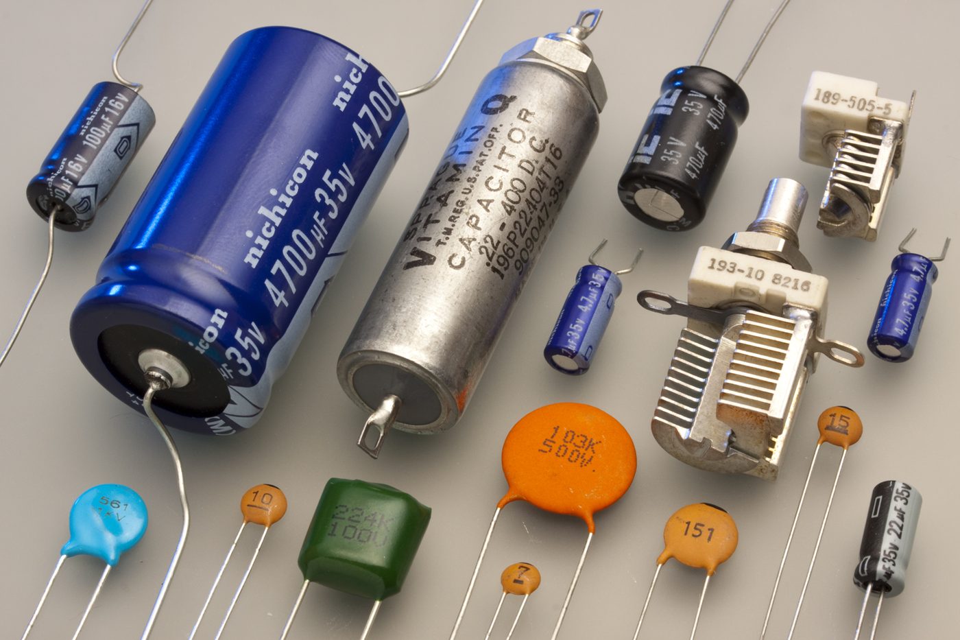
Various types of capacitors for electronics (Source: Wikipedia (Capacitor))
- Switch: A break in a line with a pivot point, showing control over circuit flow.
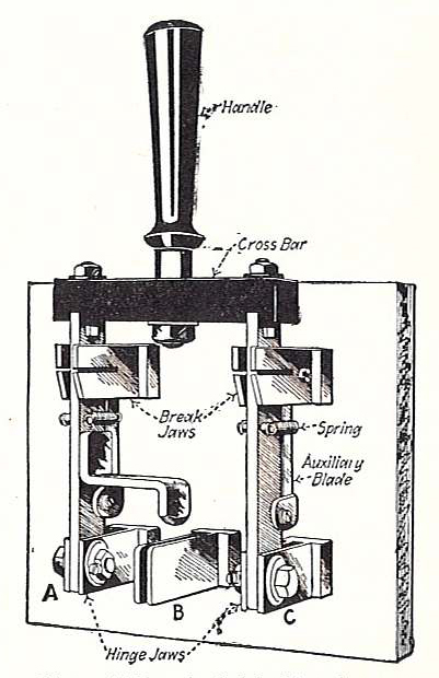
Diagram of a manual electrical switch (Source: Wikimedia Commons)
-
Light bulb: A circle with a cross inside, symbolizing illumination points in hospitals or schools.
-
Earth (Ground): A set of three decreasing horizontal lines, denoting safety grounding.
6.1.3 Electrical Abbreviations and Their Usage
Abbreviations condense long technical terms to save space and improve clarity on drawings used in sectors like county government offices and SACCOs.
- AC - Alternating Current, representing the type of electrical supply.
- DC - Direct Current, indicating unidirectional electrical flow.
- V - Voltage, the electrical potential difference.
- A - Ampere, the unit of current.
- W - Watt, the unit of power consumption.
6.1.4 Standards Governing Electrical Symbols and Abbreviations
Kenya adheres to standards ensuring electrical drawings are universally understood and safe.
- BS 3939: British Standard for electrical symbols in diagrams.
- IEC 60617: International Electrotechnical Commission standard for graphical symbols.
- KEBS (Kenya Bureau of Standards) incorporates these into national guidelines.
- ISO 128: Covers general principles for technical drawings including electrical schematics.
- OSHA Kenya regulations require compliance with these standards for workplace safety.
Practice Questions
- List and explain five common electrical symbols and their significance in a hospital electrical wiring diagram. (10 marks)
- Describe the importance of using standardized electrical abbreviations in technical drawings for a county government office. (8 marks)
- Identify four standards that govern electrical symbols and abbreviations in Kenya and explain their role in ensuring safety and clarity. (12 marks)
The rest of this chapter
🔒Create a free account to open more of this chapter.
Free: practical guides, quick cards, workplace scenarios and more.
Create a free account 🔒6.2 Meaning of Electrical Drawings
Electrical drawings are graphical representations that convey detailed information about electrical circuits and installations. They are essential for planning, constructing, troubleshooting, and maintaining electrical systems in diverse Kenyan workplaces such…
🔒6.3 Drawing of electrical diagrams e.g. block, schematic, circuit, line and wiring
Electrical diagrams are essential tools in diverse Kenyan workplaces, such as county referral hospitals, universities, and retail businesses, to communicate electrical system designs clearly and safely. These diagrams guide installation, maintenance, and troub…
🔒6.4 Drawing of Electrical and Electronic Drawings Using an Appropriate CAD Software
In Kenya’s diverse professional sectors such as hospitals, universities, and retail businesses, the use of Computer-Aided Design (CAD) software for electrical and electronic drawings has become indispensable. CAD software enhances precision, efficiency, and cl…
🔒6.5 Simulation of Electrical and Electronic Drawings
Simulation of electrical and electronic drawings is a vital stage in verifying design functionality before actual installation or manufacturing. In Kenyan contexts such as university research labs, banks, and agricultural farms, simulation helps predict system…
🔒6.6 Installation of Electrical Components in a Building Plan Using AutoCAD
In Kenya, the installation of electrical components in building plans is a critical task across various sectors including hospitals, schools, banks, and county government offices. AutoCAD software is widely used to ensure precision, compliance with standards,…
Chapter Summary
This chapter explored the fundamental electrical symbols and abbreviations essential for accurately interpreting and producing electrical drawings. It clarified the meaning of electrical drawings as vital communication tools for electrical installations and maintenance. Various types of electrical diagrams were examined in detail, including block, schematic, circuit, line, and wiring diagrams, each serving specific purposes and requiring precise construction procedures. The chapter then introduced the use of CAD software for creating detailed electrical and electronic drawings, emphasizing the importance of adhering to standard conventions. It further covered the simulation of electrical and electronic drawings, allowing verification of circuit functionality before physical implementation. Finally, the chapter demonstrated how to integrate electrical components into building plans using AutoCAD, highlighting the coordination between architectural and electrical layouts for effective installation.
Self-Assessment
🔒 PDFDownload this self-assessment, with answers
A. Written Assessment
- What is the standard symbol for a single-pole switch according to BS EN 60617? (2 marks)
- Define the purpose of a schematic electrical diagram. (3 marks)
🔒25 more in this section.
Chapter Examination Questions
🔒 PDFDownload these examination questions, with worked answers
SECTION A (40 Marks) - Answer ALL Questions
- Identify and explain the function of three common electrical symbols used in electrical drawings for a county referral hospital's lighting system. (4 marks)
- Describe the difference between a schematic diagram and a wiring diagram in the context of electrical installations in a university campus. (4 marks)
🔒25 more in this section.
