
Bell and alarm systems are critical safety and communication tools across various professional settings in Kenya. Ensuring these systems function reliably requires systematic testing and verification after installation. This chapter focuses on the key procedures involved in testing bell and alarm installations, including visual inspections and electrical continuity tests, which are essential for maintaining operational safety in institutions such as hospitals, schools, banks, and government offices.
Visual inspections are the first step in verifying the proper installation and condition of bell and alarm systems. This process involves a detailed examination of all physical components to detect any visible defects or issues that could compromise system performance. In Kenyan public hospitals, for example, routine visual checks help ensure alarms function correctly during emergencies, safeguarding patient safety.
Visual inspections aim to identify faults that may not be detectable through electrical testing alone. They help confirm that components are correctly installed, undamaged, and compliant with safety standards.
During inspection, every part of the bell and alarm system must be checked to ensure reliability and safety.
Power Supply Units: Verify that batteries or mains connections are intact and free from damage.
Enclosures and Mounts: Ensure that all protective casings are sealed and fixed to prevent environmental ingress.
Effective visual inspection requires specific tools and systematic techniques to ensure no defects are overlooked.
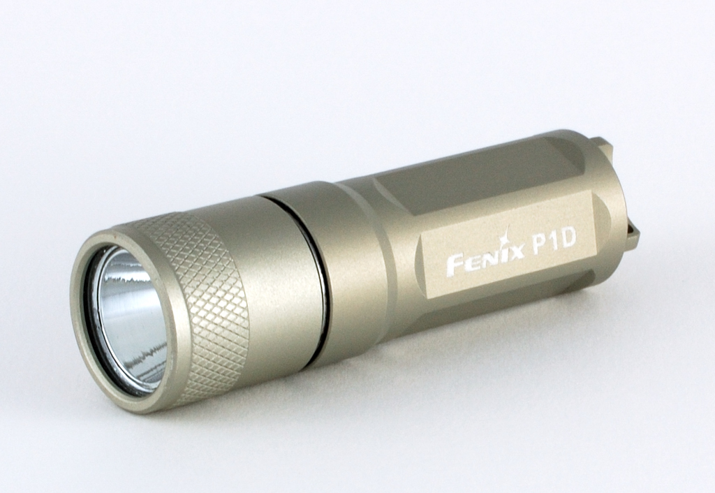
Metal flashlight Fenix P1D model (Source: Wikimedia Commons)
Magnifying Glass: Useful for detecting fine cracks or corrosion on connections.
Insulation Tester (Megger): To complement visual checks by assessing insulation quality.
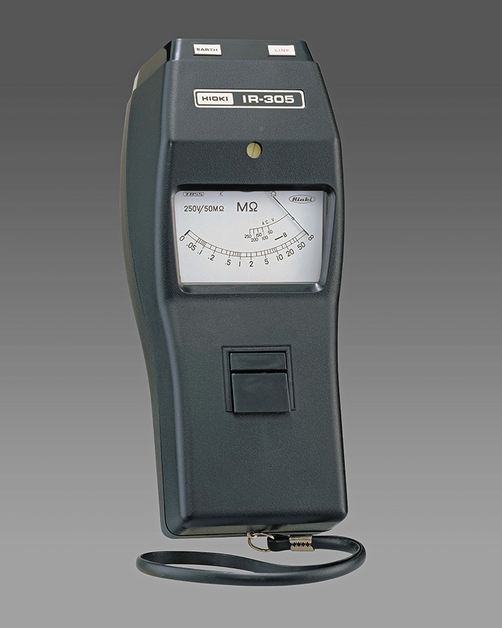
Hioki IR-305 insulation tester device (Source: Wikimedia Commons)
Visual inspection findings must be documented accurately to guide maintenance or repairs, ensuring continued system reliability.
Create a free account to open more of this chapter.
Free: practical guides, quick cards, workplace scenarios and more.
Create a free accountTesting bell and alarm installations begins with thorough visual inspections to identify any physical defects or installation errors that could affect system performance. Continuity tests are conducted next using specialized tools to ensure electrical pathways are complete, with results carefully documented and interpreted to confirm circuit integrity. Insulation resistance tests follow, assessing the quality of insulation to prevent leakage currents, using appropriate instruments and recording findings for analysis. Polarity tests verify correct wiring connections, employing dedicated equipment to avoid operational faults, with outcomes systematically documented. Earth resistance tests measure the effectiveness of grounding systems to ensure safety and proper function, utilizing specific tools and interpreting results to guarantee compliance with standards. Each testing phase involves precise use of equipment and diligent recording of results to support system reliability and safety. This comprehensive testing approach ensures bell and alarm systems operate correctly and safely in their intended environments.
Type: Individual
| Tools & Equipment | Materials |
|---|---|
| Multimeter | Bell unit 230V AC |
| Insulation resistance tester | Alarm siren 230V AC |
| Screwdriver set | Consumer control unit with circuit breakers |
| Pliers | 1.5 mm2 PVC insulated copper cable |
| Flashlight | Cable clips |
| Labels and safety signage | |
| Installation board 1m x 1m wooden |
| S/N | Item | Quantity |
|---|---|---|
| 1 | Multimeter | 1 Pc per Candidate |
| 2 | Insulation resistance tester | 1 Pc per Candidate |
| 3 | Screwdriver set | 1 set per Candidate |
| 4 | Pliers | 1 Pc per Candidate |
| 5 | Flashlight | 1 Pc per Candidate |
| 6 | Personal Protective Equipment (PPE) - gloves, goggles, dustcoat | 1 set per Candidate |
| 7 | Bell unit 230V AC | 1 Pc per Candidate |
| 8 | Alarm siren 230V AC | 1 Pc per Candidate |
| 9 | Consumer control unit with circuit breakers | 1 Pc per Candidate |
| 10 | 1.5 mm2 PVC insulated copper cable | 5 Metres per Candidate |
| 11 | Cable clips | 1 pkt per Candidate |
| 12 | Labels and safety signage | 1 set per Candidate |
| 13 | Installation board 1m x 1m wooden | 1 Pc per Candidate |
| Items to be Evaluated | Marks Available | Marks Obtained | Comments |
|---|---|---|---|
| TASK 1: Visual Inspection Process | |||
| Wore personal protective equipment (gloves, goggles, dustcoat) (Award 2 or 0) | 2 | ||
| Applied good housekeeping by ensuring clean working area before inspection (Award 2 or 0) | 2 | ||
| Checked for correct cable fixing and neat cable routing using cable clips (Award 3 or 0) | 3 | ||
| Inspected bell and alarm units for physical damage and secure fixing (Award 3 or 0) | 3 | ||
| Verified presence and legibility of safety signage and labels (Award 2 or 0) | 2 | ||
| Used multimeter to check continuity of bell and alarm circuits (Award 4 or 0) | 4 | ||
| Performed insulation resistance test on bell and alarm wiring (Award 4 or 0) | 4 | ||
| Checked consumer control unit for correct circuit breaker ratings and secure connections (Award 3 or 0) | 3 | ||
| Ensured correct color coding of wiring throughout the installation (Award 2 or 0) | 2 | ||
| Identified and reported any visible faults or defects in the installation (Award 3 or 0) | 3 | ||
| Sub-Total | 28 | ||
| PRODUCT CHECKLIST | |||
| Visual inspection report with detailed notes on defects, wiring condition, and compliance (Award 12 or 0) | 12 | ||
| Sub-Total | 12 | ||
| GRAND TOTAL | 40 | ||
Type: Individual
| Tools & Equipment | Materials |
|---|---|
| Multimeter | 1.5 mm2 PVC sheathed cable |
| Spirit level | Bell unit |
| Screwdriver | Alarm sounder |
| Pliers | 4 way consumer control unit |
| Wire stripper | 6A circuit breaker |
| PPE (gloves, goggles, boots) | Junction box |
| Deep pattress box | |
| Wood screws |
| S/N | Item | Quantity |
|---|---|---|
| 1 | 1.5 mm2 PVC sheathed cable | 5 Metres per Candidate |
| 2 | Bell unit | 1 Pc per Candidate |
| 3 | Alarm sounder | 1 Pc per Candidate |
| 4 | 4 way consumer control unit | 1 Pc per Candidate |
| 5 | 6A circuit breaker | 1 Pc per Candidate |
| 6 | Junction box | 1 Pc per Candidate |
| 7 | Deep pattress box | 2 Pcs per Candidate |
| 8 | Multimeter | 1 Pc per Candidate |
| 9 | Wood screws | 10 Pcs per Candidate |
| 10 | Spirit level | 1 Pc per Candidate |
| 11 | PPE (gloves, goggles, boots) | 1 Set per Candidate |
| Items to be Evaluated | Marks Available | Marks Obtained | Comments |
|---|---|---|---|
| TASK 1: Continuity Testing Procedure | |||
| Wore personal protective equipment (gloves, goggles, boots) (Award 1 or 0) | 1 | ||
| Applied good housekeeping practice (clean working area before starting) (Award 1 or 0) | 1 | ||
| Prepared and connected the multimeter correctly for continuity test (Award 2 or 0) | 2 | ||
| Performed continuity test on bell circuit wiring correctly (Award 3 or 0) | 3 | ||
| Performed continuity test on alarm circuit wiring correctly (Award 3 or 0) | 3 | ||
| Interpreted test results correctly and documented findings (Award 3 or 0) | 3 | ||
| Sub-Total | 13 | ||
| PRODUCT CHECKLIST | |||
| Continuity test results correctly recorded and interpreted (Award 7 or 0) | 7 | ||
| Sub-Total | 7 | ||
| GRAND TOTAL | 20 | ||