
Compiled by: John Ronoh
Water supply infrastructure design reports are essential documents that communicate the technical specifications, construction requirements, and operational considerations of water distribution systems. In Kenya, civil engineers must prepare these reports with precision to ensure compliance with regulatory standards and to facilitate the efficient delivery of potable water to communities. This chapter focuses on the critical construction appurtenances that must be included and detailed in such reports, providing a comprehensive understanding of their functions, design considerations, and applications within Kenyan water supply projects.
Construction appurtenances are the auxiliary devices and structures integrated into water supply systems to control flow, enable maintenance, and ensure system safety. These components play a vital role in the operational efficiency, reliability, and resilience of water distribution networks. In Kenya, where water infrastructure often faces challenges such as variable demand and environmental stresses, appurtenances like valves, fire hydrants, and surge tanks must be carefully designed and documented in infrastructure reports to support sustainable water management.
Valves regulate, control, and isolate the flow of water within the distribution network. Their inclusion in design reports is critical for operational flexibility and emergency management in water supply systems.
Kenyan water engineers commonly specify several valve types, each serving distinct purposes, as described under the headings below.
Designing valves requires attention to pressure ratings, material compatibility, and accessibility:
Proper installation ensures valve longevity and system reliability:
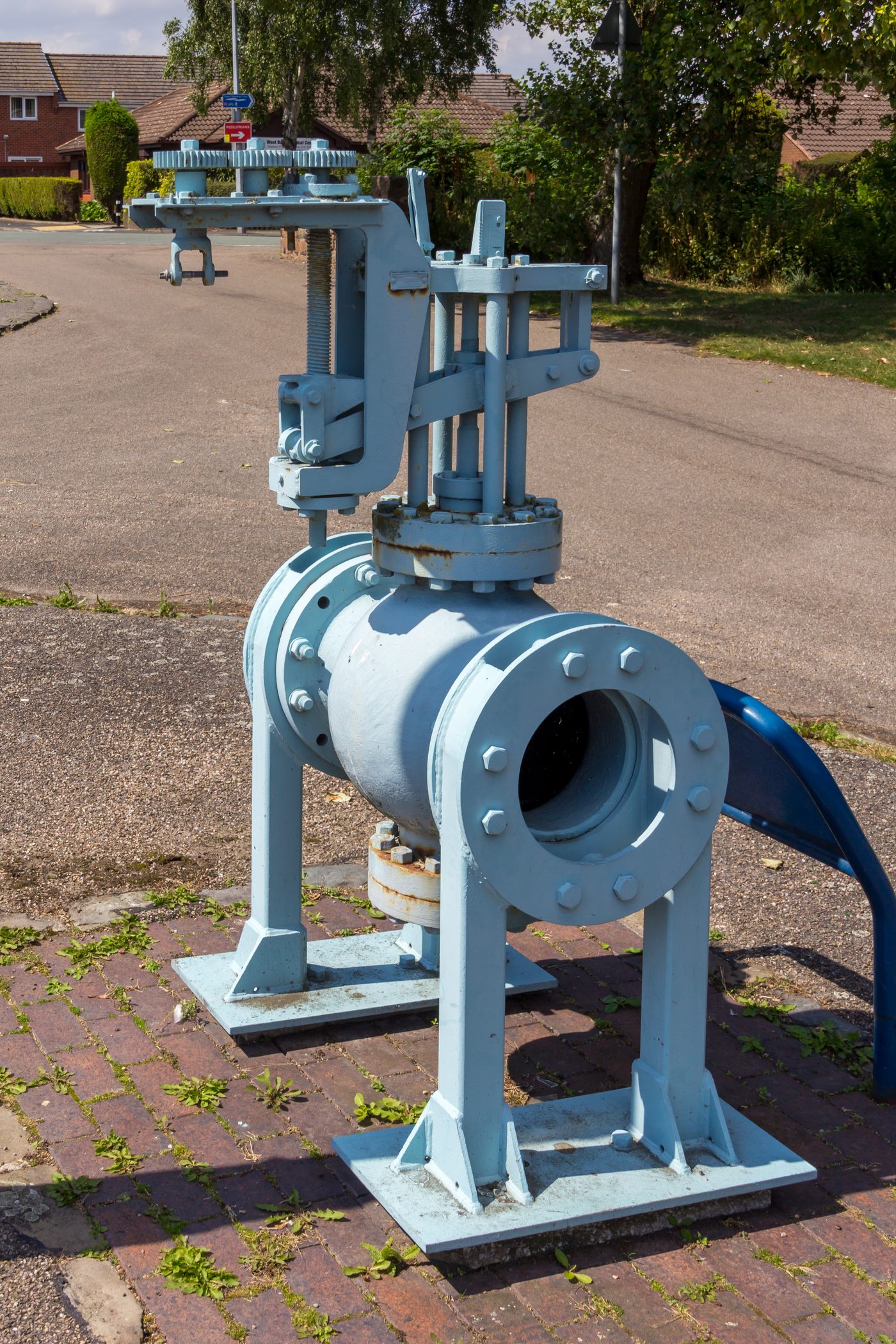
Large industrial gate valve outdoors (Source: Wikimedia Commons)
A gate valve closes the flow by lowering a flat or wedge-shaped gate across the pipe bore, operated by a handwheel or key turning a threaded stem. When fully open, the gate is lifted completely out of the flow path, so the valve causes very little head loss, which makes it the standard isolating (sluice) valve in water mains. Gate valves should be used fully open or fully closed only, because partly open gates vibrate, wear and erode. Example: a water and sanitation company in Nakuru installed resilient-seated gate valves at every branch of its distribution network so that sections could be shut off for repairs without cutting supply to the whole town.
A globe valve controls flow by moving a disc or plug towards or away from a seat inside a roughly spherical body, and the water changes direction as it passes through the valve. This design gives fine, accurate control of flow and seals tightly, so globe valves are used for throttling and regulating flow, for example on chemical dosing lines, sampling points and small bypasses. Because of the change in flow direction, globe valves cause much higher head loss than gate valves and are rarely used on large mains. Example: the chlorine dosing line at a water treatment works for a girls’ school in Kericho used small globe valves to set the dose accurately.
| Feature | Gate valve | Globe valve |
|---|---|---|
| Main use | Isolation (fully open or closed) | Regulation and throttling |
| Head loss when open | Very low | High |
| Flow control | Poor | Fine and accurate |
| Typical sizes | Small to very large mains | Mainly small pipes |
| Opening speed | Slow, many turns | Moderate |
A check valve (non-return valve) allows water to flow in one direction only and closes automatically when flow tries to reverse. It is fitted on pump delivery lines to stop water flowing back through the pump when it stops, at connections to storage tanks and at consumer connections to protect the public supply from contamination by backflow. The valve operates without any outside control, using the force of the flowing water to open and gravity, a spring or reverse flow to close. Example: on a borehole supply for a dispensary in Turkana, a check valve on the pump rising main prevented the rising main from draining back into the borehole each time the solar pump stopped.
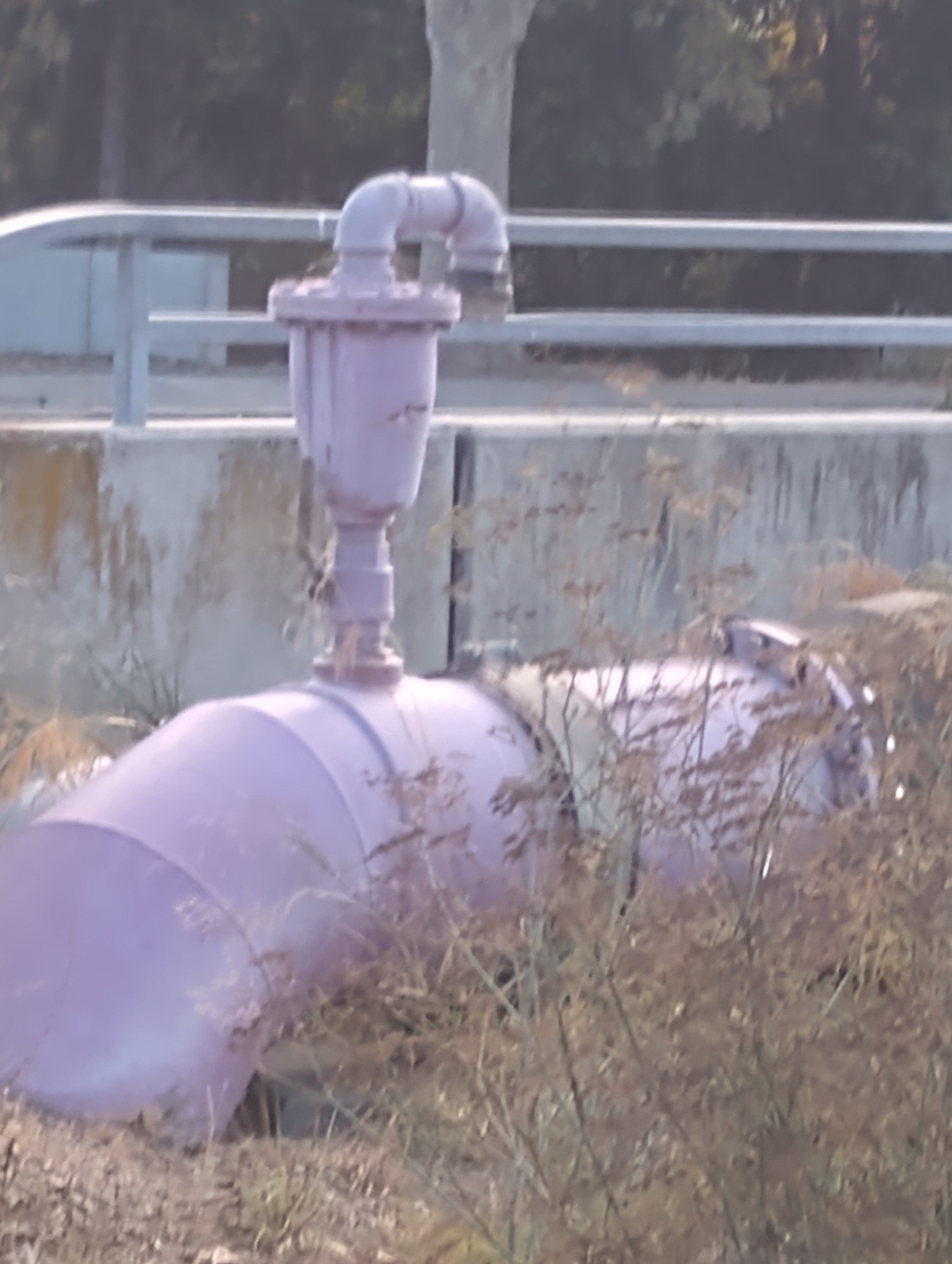
Air release valve on pipeline (Source: Wikimedia Commons)
Air relief valves remove air from pipelines and, in some types, admit air to prevent vacuum, keeping water flowing smoothly and protecting pipes. Air collects at high points in pipelines and reduces their carrying capacity, causes inaccurate metering and can lead to surges, while vacuum formed when a pipe drains can collapse thin-walled pipes or draw in contaminated water. Air valves are therefore installed at high points, at changes of gradient, after pumps and at regular intervals along long flat runs. Example: a gravity main supplying a market centre in Murang’a stopped flowing at one hill crest until an air valve was installed there, after which full flow was restored.
| Type | Function | Typical location |
|---|---|---|
| Small orifice (air release) valve | Releases small amounts of air while the pipe is under pressure | High points of pressurised mains |
| Large orifice (air and vacuum) valve | Lets out large volumes of air during filling and admits air during draining | Pump outlets, high points, valleys |
| Double (combination) air valve | Combines both functions in one valve | Most high points on transmission mains |
A pressure reducing valve (PRV) automatically lowers a high, varying upstream pressure to a lower, steady downstream pressure, regardless of changes in flow or upstream pressure. In hilly areas, water supplied from high reservoirs can reach low-lying zones at pressures high enough to burst pipes, damage fittings and increase leakage, so PRVs divide the network into pressure zones. A PRV uses a spring-loaded or pilot-operated mechanism that opens and closes in response to downstream pressure, and it is normally installed with isolating valves, a strainer, pressure gauges and a bypass for maintenance. Example: a water company serving a hilly town in Kisii installed PRVs on mains feeding the lower suburbs, reducing pipe bursts and leakage after pressure was cut from over 10 bar to about 4 bar.
A distribution point lies 120 m below the reservoir water level. Find the static pressure and state the effect of a PRV set at 4 bar.
p = ρ × g × h
p = 1,000 × 9.81 × 120
p = 1,177,200 Pa = 11.8 bar
A PRV set at 4 bar reduces the downstream pressure from about 11.8 bar to 4 bar, protecting pipes and fittings in the low-lying zone.
Fire hydrants are critical safety features in water distribution systems, providing accessible water sources for firefighting.
Strategic placement ensures effective firefighting coverage:
Maintaining hydrants is essential for emergency readiness:
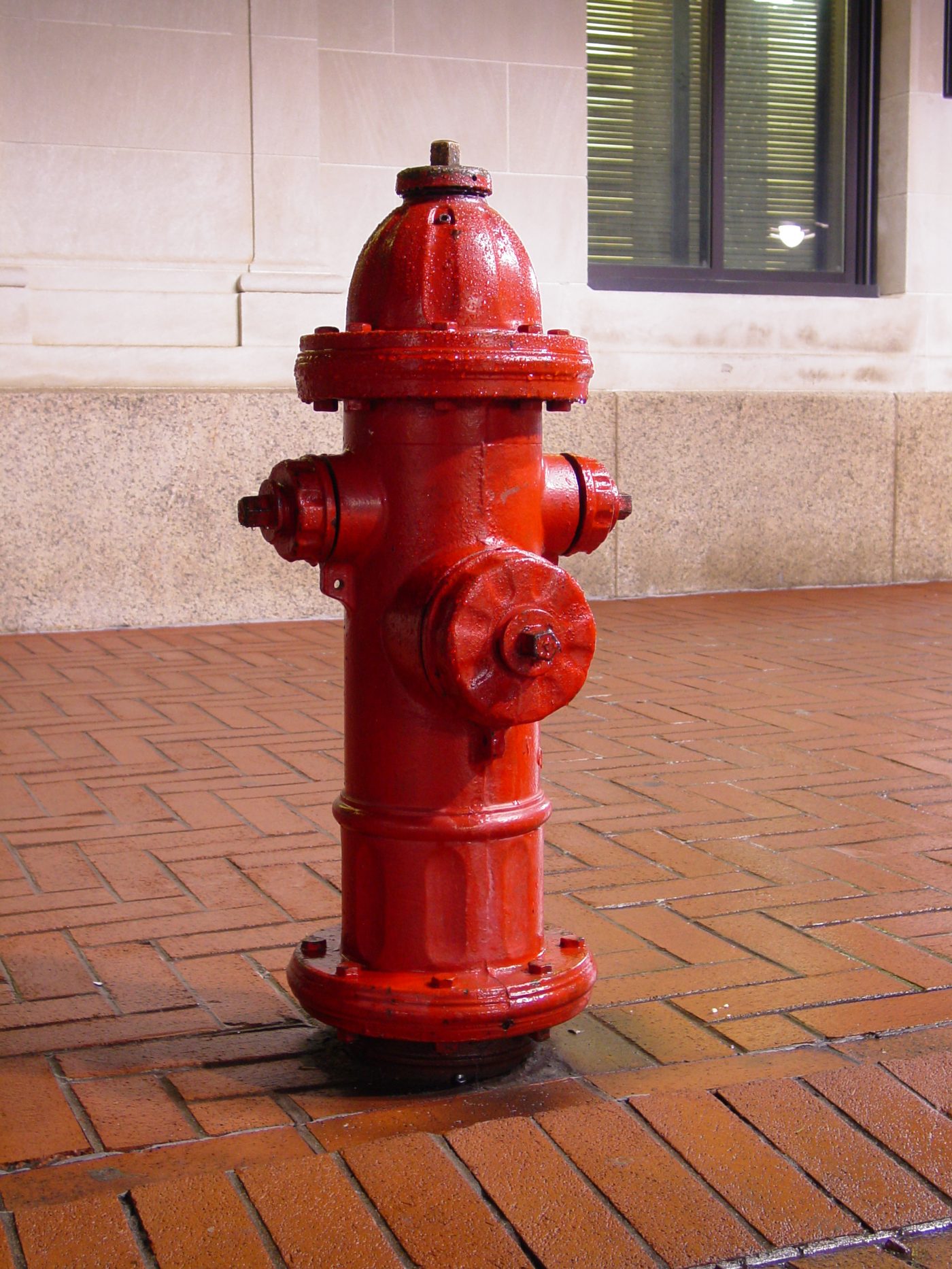
Red wet barrel fire hydrant on pavement (Source: Wikipedia (Fire hydrant))
A wet barrel hydrant is a fire hydrant whose barrel (upright body) is always full of water under pressure, with a separate valve behind each outlet. Because water is already in the barrel, firefighters can open any outlet immediately and connect hoses independently, which gives fast response. Wet barrel hydrants are suited to warm climates where there is no risk of freezing, which covers most of Kenya, but they must be robust and well protected because damage above ground can cause water loss. Example: a business park in Kisumu installed wet barrel hydrants along its internal roads so that fire crews could connect hoses within seconds of arrival.
A dry barrel hydrant keeps its main valve below ground at the base of the hydrant, so the barrel above ground is empty when the hydrant is closed and drains automatically through a drain hole after use. The valve is opened by turning an operating nut on top of the hydrant, which fills the barrel and supplies all outlets together. This design prevents freezing in cold climates and limits water loss if the hydrant is knocked over, which is also useful in areas exposed to vehicle damage or vandalism. Example: a county water department supplying a high-altitude town near Mount Kenya chose dry barrel hydrants for exposed roadside locations, where cold nights and vehicle impacts were both concerns.
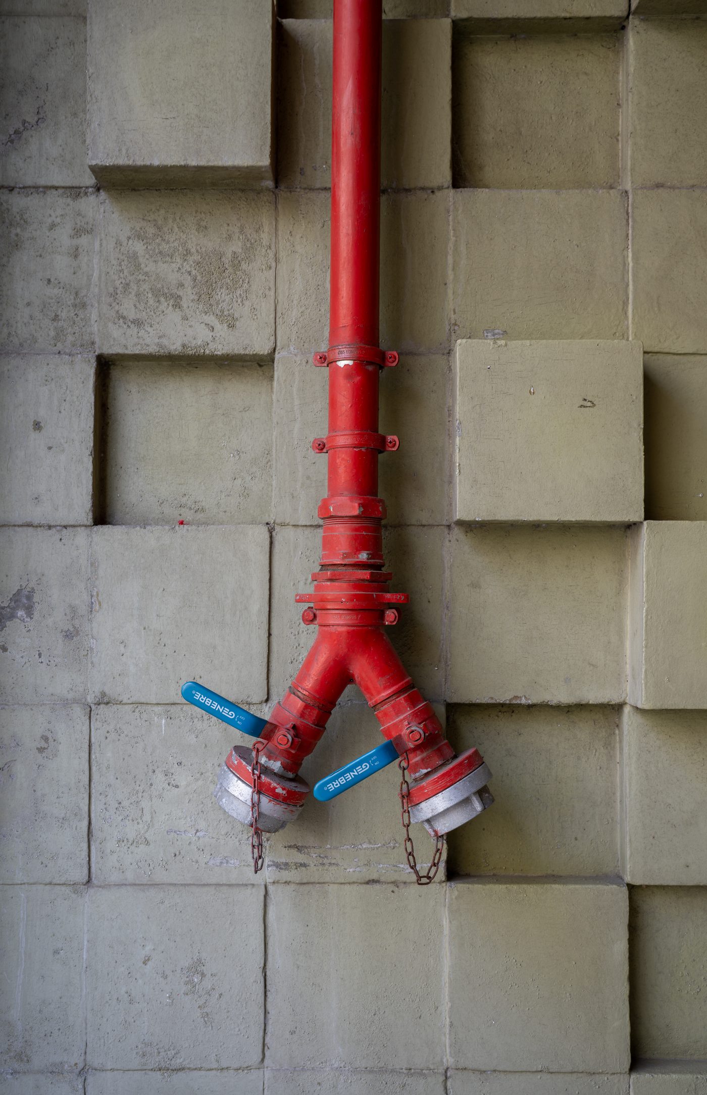
Red wall hydrant with two outlets (Source: Wikimedia Commons)
Water meters measure consumption, enabling billing and demand management within water supply systems.
Correct installation affects meter accuracy and lifespan:
Straight pipe lengths: Upstream and downstream straight pipe sections prevent turbulence, improving accuracy, this is critical in installations at Nairobi Water Company.
Protection: Meter chambers shield meters from environmental damage and unauthorized access.
Efficient meter reading supports revenue collection and water conservation:
Domestic water meters are small meters, typically 15 mm to 25 mm in size, installed on individual customer connections to measure water used by homes, small shops and offices for billing. The most common types are positive displacement meters, which measure by filling and emptying a chamber of known volume, and multi-jet or single-jet velocity meters, which measure by the speed of a rotating impeller. Domestic meters must be accurate at low flows, robust, tamper-resistant and easy to read. Example: a housing SACCO in Kitengela installed individual 15 mm meters for every house, so that each member paid only for the water used, which reduced disputes and wastage.
| Name | Specification | Use |
|---|---|---|
| Water meter | 15 mm to 25 mm positive displacement or multi-jet meter, with register in m³ | Measuring water consumed by the customer |
| Inlet isolating valve | Gate or ball valve | Isolating the meter for replacement |
| Strainer | Mesh filter, often built into the meter | Protecting the meter from grit |
| Non-return valve | Small check valve | Preventing backflow from the property |
| Unions and couplings | Brass or plastic connectors | Allowing easy removal of the meter |
| Meter box or chamber | Plastic box or masonry chamber with lockable cover | Protecting the meter |
Bulk meters are large meters, usually 50 mm and above, installed on transmission mains, reservoir outlets, zone inlets and large consumers such as factories, hospitals and institutions to measure large volumes of water. They allow water utilities to measure water produced and supplied to each zone, calculate non-revenue water (water lost through leaks, theft and errors) and bill large consumers accurately. Common types include Woltmann (turbine) meters and electromagnetic meters, often with data loggers for continuous recording. Example: a water company in Eldoret installed bulk meters at the inlets of each supply zone and found that one zone was losing over 40% of its water, leading to targeted leak repairs.
An electromagnetic (magnetic flow) meter measures the velocity of water using Faraday’s law of electromagnetic induction: water, which conducts electricity, flowing through a magnetic field created by coils around the pipe produces a small voltage proportional to its velocity, which electrodes measure and convert into flow rate. Because it has no moving parts and no obstruction in the pipe, it causes no head loss, does not wear and remains accurate over a wide range of flows, which makes it ideal for bulk metering of treated and raw water. It requires an electrical power supply or long-life battery and is more expensive than mechanical meters. Example: the treatment works serving a county water project in Embu used electromagnetic meters on its outlet mains to provide accurate continuous flow data to its control room.
Chambers are underground enclosures that house valves, connections, or other appurtenances, facilitating operation and maintenance.
Chamber design ensures durability and safety:
Ensuring safe and effective chamber use involves:
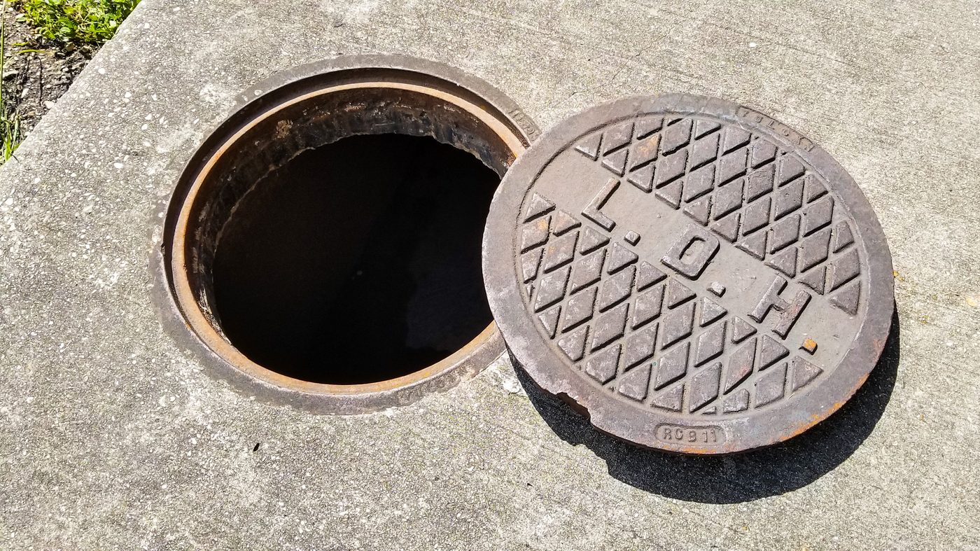
Open access cover on concrete surface (Source: Wikipedia (Manhole cover))
A meter chamber is a small underground or partly buried enclosure that houses a water meter and its associated fittings, protecting it from damage, tampering and weather while allowing it to be read and maintained. For domestic connections, a small precast or masonry box is usually enough, while bulk meters need larger reinforced concrete chambers with space for the meter, valves, strainer and dismantling joint, and room for a person to work. The chamber must be sited where it is accessible to the meter reader, usually at the property boundary. Example: a hotel in Nanyuki had its bulk meter housed in a reinforced concrete chamber at the gate, with a lockable cover so that utility staff could read it without entering the hotel premises.
A valve chamber is an underground enclosure built around a valve, such as a gate valve, air valve, washout or pressure reducing valve, to protect it and allow operators to reach and maintain it. Small buried valves may only need a surface box for the operating key, but larger valves and valve assemblies need a chamber with enough space to operate, inspect and remove the valve. Chambers must be built so that the pipeline does not rest on the chamber walls, preventing damage from settlement, and must drain or be pumped to stay dry. Example: on a transmission main supplying a sugar factory in Mumias, each large isolating valve was housed in a reinforced concrete chamber with step irons and a lockable cover.
Meter chambers are specialized enclosures designed to protect water meters from environmental damage and unauthorized interference.
Meter chambers incorporate design elements that safeguard meters:
Proper installation is crucial for meter accuracy and longevity:
Maintaining meter chambers enhances system reliability:
Surge tanks mitigate pressure fluctuations in water supply systems, protecting pipelines and equipment from water hammer effects.
Surge tanks serve as protective devices in pressurized systems:
Different surge tank designs suit varied system requirements:
Design parameters include tank volume, height, and placement relative to pipelines, calculated based on system pressure and flow characteristics common in Kenyan water supply projects.
Water flowing at 1.5 m/s in a pipeline is stopped suddenly by a fast-closing valve. Taking the pressure wave speed as 1,000 m/s, estimate the pressure rise.
Δp = ρ × c × Δv
Δp = 1,000 × 1,000 × 1.5
Δp = 1,500,000 Pa = 15 bar
A pressure rise of this size could burst the pipe, which is why surge tanks, surge vessels and slow-closing valves are provided.
Proper integration of surge tanks ensures system longevity:
Create a free account to open more of this chapter.
Free: practical guides, quick cards, workplace scenarios and more.
Create a free accountThis chapter covers the preparation of a water supply infrastructure design report, beginning with an overview of construction appurtenances such as various types of valves including gate, globe, check, air relief, and pressure reducing valves. It then discusses fire hydrants, distinguishing between wet barrel and dry barrel types, as well as different meters including domestic, bulk, and electromagnetic meters. The chapter also addresses chambers used for meters and valves along with surge tanks that help regulate pressure fluctuations. Technical specifications for materials and equipment are outlined to ensure quality and suitability for water supply systems. The bill of quantities section explains the measurement of works and cost estimations necessary for budgeting and project planning. The technical design report section delves into structural analysis topics such as moments in beams, shear forces, bending moments, graphical representations, section properties, and the theory of simple bending. It further examines forces in frames, deflection in beams, and the design of reinforced concrete, timber, and steel structures, including welded connections. The chapter concludes with guidance on technical report writing and assembling the comprehensive design report.
Type: Individual
| Tools & Equipment | Materials |
|---|---|
| Pipe Wrench | Gate Valve 50mm |
| Adjustable Spanner | Globe Valve 50mm |
| Teflon Tape Roll | Check Valve 50mm |
| Galvanized Steel Pipe 50mm diameter | |
| Pipe Flanges 50mm | |
| Gaskets 50mm | |
| Bolts and Nuts for 50mm flanges | |
| Threaded Pipe Couplings 50mm |
| S/N | Item | Quantity |
|---|---|---|
| 1 | Gate Valve 50mm | 1 Pc per Candidate |
| 2 | Globe Valve 50mm | 1 Pc per Candidate |
| 3 | Check Valve 50mm | 1 Pc per Candidate |
| 4 | Galvanized Steel Pipe 50mm diameter, 1.5m length | 3 Pcs per Candidate |
| 5 | Pipe Flanges 50mm | 6 Pcs per Candidate |
| 6 | Gaskets 50mm | 6 Pcs per Candidate |
| 7 | Bolts and Nuts for 50mm flanges | 12 Sets per Candidate |
| 8 | Threaded Pipe Couplings 50mm | 2 Pcs per Candidate |
| 9 | Pipe Wrench | 1 Pc per Candidate |
| 10 | Adjustable Spanner | 1 Pc per Candidate |
| 11 | Teflon Tape Roll | 1 Roll per Candidate |
| 12 | Safety Helmet | 1 Pc per Candidate |
| 13 | Safety Gloves | 1 Pair per Candidate |
| 14 | Safety Boots | 1 Pair per Candidate |
| Items to be Evaluated | Marks Available | Marks Obtained | Comments |
|---|---|---|---|
| TASK 1: Safety and Preparation | |||
| Candidate wears all prescribed PPE including helmet, gloves, and safety boots (Award 1 mark or zero) | 1 | ||
| Candidate observes environmental safety and proper site/workshop arrangement (Award 1 mark or zero) | 1 | ||
| Sub-Total | 2 | ||
| TASK 2: Valve Selection and Interpretation | |||
| Candidate correctly identifies and selects gate valve for flow isolation (Award 1 mark or zero) | 1 | ||
| Candidate correctly identifies and selects globe valve for flow regulation (Award 1 mark or zero) | 1 | ||
| Candidate correctly identifies and selects check valve to prevent backflow (Award 1 mark or zero) | 1 | ||
| Candidate interprets the working drawing correctly for valve placement and orientation (Award 2 marks or zero) | 2 | ||
| Sub-Total | 5 | ||
| TASK 3: Installation Procedures | |||
| Candidate uses pipe wrench and adjustable spanner correctly during installation (Award 1 mark or zero) | 1 | ||
| Candidate applies Teflon tape correctly to threaded joints (Award 1 mark or zero) | 1 | ||
| Candidate installs gate valve with correct flange and gasket alignment (Award 2 marks or zero) | 2 | ||
| Candidate installs globe valve with correct flange and gasket alignment (Award 2 marks or zero) | 2 | ||
| Candidate installs check valve with correct orientation and flange alignment (Award 2 marks or zero) | 2 | ||
| Candidate tightens bolts and nuts to secure all valves without damaging flanges (Award 1 mark or zero) | 1 | ||
| Sub-Total | 9 | ||
| PRODUCT CHECKLIST | |||
| Correct valve types installed at specified locations as per drawing (Award 3 marks or zero) | 3 | ||
| All valves installed with correct orientation and no leaks (tested visually) (Award 3 marks or zero) | 3 | ||
| Piping section including valves is properly aligned, level, and securely fixed (Award 2 marks or zero) | 2 | ||
| Dimensions of assembled pipe section including valves conform to 1500mm length ±5mm (Award 2 marks or zero) | 2 | ||
| Sub-Total | 10 | ||
| GRAND TOTAL | 26 | ||
Type: Individual
| Tools & Equipment | Materials |
|---|---|
| Spirit level | Air relief valve, 50mm diameter |
| Tape measure | Pressure reducing valve, 80mm diameter |
| Adjustable spanner | Steel pipe, 80mm diameter |
| Pipe wrench | Pipe flanges, 80mm diameter |
| Marker pen | Gaskets for 80mm flanges |
| Bolts and nuts for flange connections | |
| PTFE tape |
| S/N | Item | Quantity |
|---|---|---|
| 1 | Air relief valve, 50mm diameter | 1 Pc per Candidate |
| 2 | Pressure reducing valve, 80mm diameter | 1 Pc per Candidate |
| 3 | Steel pipe, 80mm diameter, 2m length | 2 Pcs per Candidate |
| 4 | Pipe flanges, 80mm diameter | 4 Pcs per Candidate |
| 5 | Gaskets for 80mm flanges | 2 Pcs per Candidate |
| 6 | Bolts and nuts for flange connections | 8 Pcs per Candidate |
| 7 | PTFE tape | 1 roll per 5 Candidates |
| 8 | Spirit level | 1 Pc per Candidate |
| 9 | Tape measure | 1 Pc per Candidate |
| 10 | Adjustable spanner | 1 Pc per Candidate |
| 11 | Pipe wrench | 1 Pc per Candidate |
| 12 | Marker pen | 1 Pc per Candidate |
| 13 | Safety boots | 1 pair per Candidate |
| 14 | Safety gloves | 1 pair per Candidate |
| 15 | Safety helmet | 1 Pc per Candidate |
| Items to be Evaluated | Marks Available | Marks Obtained | Comments |
|---|---|---|---|
| TASK 1: Safety and Preparation | |||
| Candidate wore all prescribed PPE (safety boots, gloves, helmet) (Award 1 mark or zero) | 1 | ||
| Observed environmental safety: safe use of tools and proper workspace arrangement (Award 1 mark or zero) | 1 | ||
| Sub-Total | 2 | ||
| TASK 2: Interpretation and Layout | |||
| Correct interpretation of the working drawing layout for valve installation (Award 4 marks or zero) | 4 | ||
| Used tape measure and marker pen correctly to mark pipe lengths and valve positions (Award 1 mark or zero) | 1 | ||
| Used spirit level to ensure horizontal alignment of pipe segments (Award 1 mark or zero) | 1 | ||
| Sub-Total | 6 | ||
| TASK 3: Assembly and Installation | |||
| Applied PTFE tape correctly on threaded connections (Award 1 mark or zero) | 1 | ||
| Assembled air relief valve and pressure reducing valve with correct flange connections (Award 2 marks or zero) | 2 | ||
| Tightened flange bolts correctly using spanner and pipe wrench (Award 1 mark or zero) | 1 | ||
| Sub-Total | 4 | ||
| PRODUCT CHECKLIST | |||
| Final layout plan shows correct valve positions with 2000mm pipe length, valves dimensioned 50mm and 80mm diameters respectively (Award 3 marks or zero) | 3 | ||
| Assembly is leak-proof and properly aligned (horizontal level confirmed) (Award 3 marks or zero) | 3 | ||
| Valve functions correctly explained in candidate’s report (Award 3 marks or zero) | 3 | ||
| Sub-Total | 9 | ||
| GRAND TOTAL | 21 | ||