
By the end of this chapter, you will be able to:
Mastering these skills will help you confidently read and create electrical drawings, an essential part of ensuring safe and effective electrical installations in real-world civil engineering projects.
Compiled by: Michael Githaiga
Interpretation of electrical drawings is a fundamental skill for civil engineers working on infrastructure projects in Kenya. These drawings provide detailed information on electrical installations within buildings and civil structures, ensuring proper coordination with architectural and structural elements. Understanding electrical circuit symbols and the ability to sketch circuit layouts accurately is vital for effective communication with electrical engineers and ensuring compliance with safety and regulatory standards.
Electrical circuit symbols are standardized graphical representations used in electrical drawings to denote components and devices within a circuit. Mastery of these symbols enables civil engineers to read and interpret electrical layouts accurately, facilitating integration with civil works. In Kenya, adherence to international standards such as BS 3939 and IEC symbols ensures consistency and clarity in documentation.
Standard electrical symbols are universally recognized icons used to depict electrical components on drawings. The following are essential symbols regularly encountered in civil engineering electrical plans:
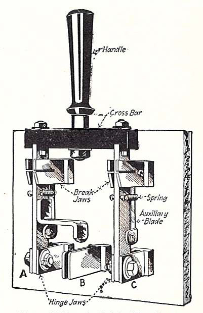
Diagram of a manual electrical switch (Source: Wikimedia Commons)
Resistors: Shown as a zig-zag line, resistors limit current flow and protect circuits.
Capacitors: Depicted by two parallel lines with a gap, capacitors store electrical charge.
Transformers: Illustrated by two coils or loops, transformers change voltage levels.
Lamps/Light Bulbs: Shown as a circle with a cross inside, indicating lighting fixtures.
Motors: Represented by a circle with the letter 'M' inside, motors convert electrical energy to mechanical energy.
Ground/Earth: Indicated by a set of horizontal lines decreasing in length, grounding symbols ensure safety by connecting to earth.
Each symbol follows BS and IEC standards to maintain uniformity across drawings, which is crucial for multidisciplinary teams working on Kenyan construction sites.
Understanding the significance of each electrical symbol is critical for interpreting circuit functionality and safety requirements:
Civil engineers must appreciate these symbols’ roles to coordinate structural provisions like conduit spaces, cable trays, and mounting points with electrical requirements.
Create a free account to open more of this chapter.
Free: practical guides, quick cards, workplace scenarios and more.
Create a free accountThis chapter focused on interpreting electrical drawings by first exploring standard electrical circuit symbols and their significance in representing various electrical components clearly and consistently. It then covered techniques for accurate electrical circuit sketching, emphasizing the need to integrate electrical layouts seamlessly with architectural designs to ensure practical and efficient installations. Students learned how to create sketches based on given specifications, reinforcing precision and adherence to design requirements. The chapter also highlighted the importance of connection layouts in electrical systems, guiding learners on how to draw effective connection diagrams that facilitate understanding and maintenance. Additionally, the evaluation of existing connection layouts was discussed to identify areas for improvement and enhance system reliability. Overall, the chapter provided a comprehensive approach to reading, sketching, and analyzing electrical drawings critical for civil engineering projects.
Type: Individual
| Tools & Equipment | Materials |
|---|---|
| Computer with CADD software installed | A3 size printing papers |
| Printer capable of A3 printing | Blank writable CD |
| Scientific Calculator |
| S/N | Item | Quantity |
|---|---|---|
| 1 | A3 size printing papers | 3 Pcs per Candidate |
| 2 | Blank writable CD | 1 Pc per Candidate |
| 3 | Computer with CADD software installed | 1 Pc per Candidate |
| 4 | Printer capable of A3 printing | 1 Pc per 5 Candidates |
| 5 | Scientific Calculator | 1 Pc per Candidate |
| Items to be Evaluated | Marks Available | Marks Obtained | Comments |
|---|---|---|---|
| TASK 1: Identification of electrical circuit symbols | |||
| Wears appropriate PPE before starting the task (Award 2 marks for correct PPE use or zero) | 2 | ||
| Correctly identifies each of the 15 electrical circuit symbols on the schematic (Award 1 mark for each correctly identified symbol or zero) | 10 | ||
| Explains the significance of each identified electrical symbol accurately (Award 1 mark for each correct explanation or zero) | 15 | ||
| Uses appropriate terminology related to electrical circuit symbols (Award 3 marks for consistent correct terminology or zero) | 3 | ||
| Sub-Total | 30 | ||
| PRODUCT CHECKLIST | |||
| Schematic drawing produced on A3 paper with all 15 electrical circuit symbols clearly and correctly represented (Award 10 marks for clear, accurate, and scaled schematic or zero) | 10 | ||
| Drawing dimensions: 420mm length x 297mm width (A3 size) confirmed (Award 5 marks for correct dimensions or zero) | 5 | ||
| Drawing saved correctly on blank writable CD (Award 5 marks for successful saving or zero) | 5 | ||
| Sub-Total | 20 | ||
| GRAND TOTAL | 50 | ||
Type: Individual
| Tools & Equipment | Materials |
|---|---|
| HB Pencil | A3 Drawing Paper |
| Eraser | |
| Ruler 30cm | |
| Set Squares (45° and 60°) |
| S/N | Item | Quantity |
|---|---|---|
| 1 | HB Pencil | 1 Pc per Candidate |
| 2 | Eraser | 1 Pc per Candidate |
| 3 | Ruler 30cm | 1 Pc per Candidate |
| 4 | A3 Drawing Paper | 3 Sheets per Candidate |
| 5 | Set Squares (45° and 60°) | 1 Set per Candidate |
| 6 | Scientific Calculator | 1 Pc per Candidate |
| Items to be Evaluated | Marks Available | Marks Obtained | Comments |
|---|---|---|---|
| TASK 1: Circuit Sketching Process | |||
| Wears appropriate PPE before starting (Award 1 mark for correct PPE usage or zero) | 1 | ||
| Sets out drawing area correctly on A3 paper (Award 2 marks for neat and correct layout or zero) | 2 | ||
| Uses appropriate scale approximately 1:2 for circuit sketch (Award 2 marks for correct scale or zero) | 2 | ||
| Applies correct symbols for switch, fuse, lamp, and supply (Award 4 marks for accurate and standard symbols or zero) | 4 | ||
| Connects components with neat and continuous lines (Award 3 marks for neat, continuous, and logical connections or zero) | 3 | ||
| Labels each component clearly and correctly (Award 3 marks for clear and correct labeling or zero) | 3 | ||
| Sub-Total | 15 | ||
| PRODUCT CHECKLIST | |||
| Final sketch dimensions 250mm x 180mm within 5mm tolerance (Award 3 marks for correct dimensions or zero) | 3 | ||
| Correct and standard electrical symbols used for switch, fuse, lamp, and supply (Award 5 marks for all correct symbols or zero) | 5 | ||
| Circuit connections are logical, continuous, and without breaks (Award 4 marks for proper connections or zero) | 4 | ||
| Labels are accurate, legible, and correctly positioned (Award 3 marks for labeling or zero) | 3 | ||
| Sub-Total | 15 | ||
| GRAND TOTAL | 30 | ||
At the start of this chapter we promised you would be able to:
Tick each one you can genuinely do.
So, are you there yet?
You're competent when you can confidently do 50% or more of what this chapter promised.
Sign in to record how you're doing.