
By the end of this chapter, you will be able to:
Mastering these skills will help you confidently analyze and design safe, efficient framed structures in your trade.
Compiled by: Samuel Wachira
Structural analysis of two-dimensional (2D) framed structures is a fundamental skill for civil engineers working on building and infrastructure projects across Kenya. Understanding how forces distribute within these frames ensures safety, serviceability, and economic use of materials. This chapter focuses on the mathematical analysis of 2D framed structures, emphasizing methods to determine internal forces and reactions in pin-jointed and rigid-jointed frames commonly found in buildings, bridges, and other civil engineering works.
2D framed structures consist of interconnected elements arranged in a plane, designed to support loads and transfer them safely to foundations. These frames are prevalent in Kenyan construction, from multistory buildings in Nairobi to agricultural storage sheds in rural counties. Understanding their characteristics enables engineers to select appropriate analysis methods and design safe, efficient structures.
Joints are connection points which may be pinned or rigid, influencing force transmission. In a pin-jointed frame, members are connected by pins (or connections that act like pins) that allow the members to rotate freely, so no bending moment passes through the joint and, when loads act only at the joints, each member carries a pure axial force of tension or compression. In a rigid-jointed frame, members are connected so firmly, by welding, bolted end plates or monolithic concrete, that the angle between them stays the same under load, so the joint transfers bending moment and shear as well as axial force. This difference decides how the structure behaves, what it can be made of and how it is analysed. Example: the steel roof trusses of a cereal store for a farmers' cooperative are treated as pin-jointed, while the reinforced concrete frame of its office block is rigid-jointed.
| Feature | Pin-jointed frame | Rigid-jointed frame |
|---|---|---|
| Joint behaviour | Members free to rotate at joints | Angles between members stay fixed |
| Forces in members | Axial tension or compression only | Axial force, shear force and bending moment |
| Moment at joints | Zero | Transferred between members |
| Stability | Needs triangulation (triangles) to be stable | Stable without triangles because joints resist rotation |
| Typical members | Slender angles, tubes, timber sections | Heavier beams and columns, I-sections, RC members |
| Typical structures | Roof trusses, bridge trusses, towers | Portal frames, multi-storey building frames |
| Analysis | Method of joints or sections | Moment distribution, slope-deflection, software |
| Determinacy check | m + r = 2j | 3m + r = 3j |
A frame is statically determinate if all internal forces and reactions can be found using equilibrium equations alone. If additional compatibility conditions are needed, the frame is statically indeterminate. This classification influences the choice of analysis method. The checks use m = number of members, r = number of support reactions and j = number of joints.
Given: A truss has 9 members and 6 joints, with a pin support (2 reactions) and a roller support (1 reaction). Check its determinacy.
m + r = 9 + 3 = 12
2j = 2 × 6 = 12
Answer: m + r = 2j, so the truss is statically determinate.
Given: A single-bay portal frame has 3 members (two columns and a beam), 4 joints (two column bases and two knees) and two fixed bases, each giving 3 reactions. Find its degree of indeterminacy.
3m + r = 3 × 3 + 6 = 15
3j = 3 × 4 = 12
Degree of indeterminacy = 15 − 12
Answer: The frame is indeterminate to the third degree.
Trusses and frames are the two main families of 2D framed structures. Trusses are triangulated assemblies of straight members, assumed pin-jointed, that span long distances with little material and are used for roofs, bridges and towers. Frames are rigid-jointed assemblies of beams and columns that resist load by bending and are used for buildings, warehouses and portal-framed sheds. Example: a new vocational training centre has a Fink timber truss roof over its classrooms and a steel portal frame over its workshop, where a clear floor is needed for machines.
| Truss type | Description | Typical use |
|---|---|---|
| King post | Central vertical post with two inclined struts | Short-span house roofs, up to about 8 m |
| Queen post | Two vertical posts with a straining beam between them | Medium-span roofs, about 8 to 14 m |
| Fink | Rafters supported by a W-pattern of struts | Common pitched roofs for houses and schools |
| Pratt | Verticals in compression, diagonals in tension | Bridges and flat or low-pitch roofs |
| Howe | Diagonals in compression, verticals in tension | Timber bridges and roofs |
| Warren | Diagonals only, forming equilateral triangles | Bridges, footbridges and long-span roofs |
2D frames are composed of straight members connected at nodes, forming a planar system. The geometry defines the shape and size of the frame, affecting stiffness and load distribution. The primary components include:
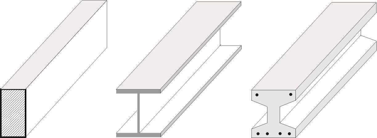
Three types of structural beams in carpentry (Source: Wikimedia Commons)
Frames in civil engineering are subjected to various loads that induce internal forces, and each load type affects the frame differently, requiring careful analysis to ensure safety:
Stability ensures the frame maintains its geometry under load without collapse, and engineers must evaluate the following risks during design and analysis:
Create a free account to open more of this chapter.
Free: practical guides, quick cards, workplace scenarios and more.
Create a free accountThis chapter explored the characteristics of two-dimensional framed structures, highlighting the fundamental differences between pin-jointed and rigid-jointed frames and illustrating these concepts through examples in trusses and frames. It then examined the key assumptions and methods used in structural analysis, focusing on the method of joints and the method of sections as primary techniques for evaluating internal forces. The chapter proceeded to analyze real-world 2D frames by demonstrating how to calculate forces in truss members and determine support reactions for various frame types. Practical application was emphasized through detailed examples involving roof trusses and portal frames, showing how theoretical principles translate into structural design and assessment. Throughout the chapter, the integration of theory with practice reinforced the importance of accurate force analysis in ensuring the stability and safety of framed structures.
A simple 2D pin-jointed truss has a horizontal top chord member of length 6 m and a vertical member of length 4 m forming a right angle. Calculate the length of the diagonal member connecting the bottom left joint to the top right joint. (2 marks)
A roof truss is supported at two points 8 m apart. The truss carries a uniformly distributed load of 12 kN/m along the top chord. Calculate the vertical reaction at each support. (3 marks)
At the start of this chapter we promised you would be able to:
Tick each one you can genuinely do.
So, are you there yet?
You're competent when you can confidently do 50% or more of what this chapter promised.
Sign in to record how you're doing.