Building Technology  ·  Level 5
Technical Drawing
Chapter 2: Produce plane geometry drawings
📚 6 Topics
⚑ What you will be able to do

By the end of this chapter, you will be able to:

  • Identify different types of lines used in technical drawings and explain what they mean following standard drawing rules.
  • Construct various geometric shapes accurately using the correct drawing conventions.
  • Create different angles correctly by applying basic trigonometry principles.
  • Measure angles precisely with the right tools to ensure accuracy.
  • Bisect angles carefully and correctly following standard drawing practices.
  • Produce clear freehand sketches of geometric shapes, tools, equipment, and diagrams.

Mastering these skills will help you communicate your ideas clearly and professionally in the technical trade world.

Compiled by: Rose Apiyo

Producing accurate plane geometry drawings is fundamental for Building Technology professionals in Kenya. These drawings form the basis for designing, planning, and executing construction projects, ensuring all stakeholders have a clear understanding of spatial relationships and dimensions. Mastery of line types and conventions according to recognized standards allows for effective communication and compliance with regulatory requirements, reducing errors and enhancing project quality.

2.1 Types of lines used in drawings

In Building Technology, different types of lines convey specific information on technical drawings. Understanding these line types is essential for clear representation of objects, boundaries, and features in plans, sections, and elevations. Kenyan professionals rely on British Standards (BS 8888) and ISO conventions adapted locally to ensure drawings are universally interpretable and meet industry standards.

2.1.1 Purpose of different line types in plane geometry drawings

Different line types serve distinct purposes that help differentiate elements on a drawing. Their correct use avoids ambiguity and improves readability, which is critical on construction sites and in project documentation.
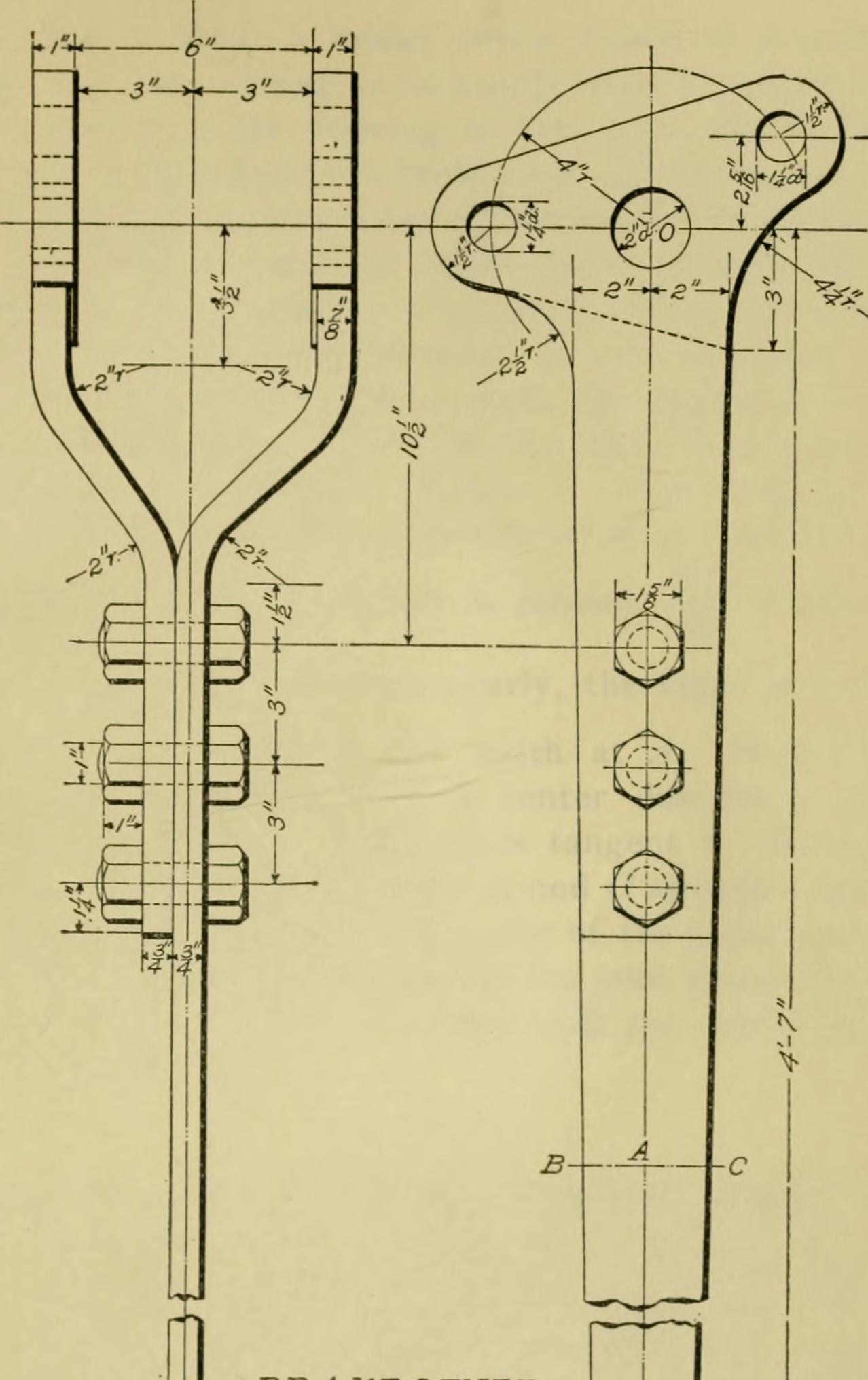
  • Object Lines represent visible edges of objects. They are thick continuous lines that outline the shape and form of building components.
  • Hidden Lines indicate edges not visible in the current view. These are medium thickness dashed lines that help visualize internal or obscured features.
  • Centre Lines mark axes of symmetry or the center of circles and arcs. They are thin lines alternating long and short dashes, helping to locate geometric centers.
  • Dimension Lines show distances and measurements. These thin continuous lines have arrowheads at ends and are placed between extension lines.

Engineering drawing with dimension lines shown
Engineering drawing with dimension lines shown (Source: Wikimedia Commons)

  • Extension Lines extend from the object to dimension lines, indicating the exact points being measured. They are thin and do not touch the object lines.

A technical drawing illustrating the use of extension lines and dimens
A technical drawing illustrating the use of extension lines and dimens (Source: 59d646f026634d9a)

  • Cutting Plane Lines indicate where a section is taken. These are thick dashed lines with arrows showing the direction of the section view.

2.1.2 Characteristics and standards for line types in building drawings

Kenyan Building Technology professionals adhere to BS 8888 and ISO 128 standards for line types, ensuring consistency and clarity.

  • Line Weight varies according to line function. Object lines are thick (0.7 to 1.0 mm), hidden lines medium (0.35 to 0.5 mm), and center lines thin (0.18 to 0.35 mm).
  • Line Style includes continuous, dashed, chain, and dotted patterns. Each pattern corresponds to specific features such as visible edges or hidden details.
  • Colour in manual drawings is rarely used; however, CAD drawings may employ colours for clarity, but final prints must conform to monochrome standards.
  • Scale Considerations affect line thickness; smaller scales require finer lines to avoid clutter, while larger scales permit bolder lines.
  • Title Block and Legend must clearly define line types used in the drawing to assist readers unfamiliar with the specific conventions.

2.1.3 Drawing tools and equipment for producing line types

Name Specification Use
Mechanical Pencil 0.5 mm lead, HB grade Producing fine continuous and dashed lines with precision
Technical Pen 0.35 mm and 0.7 mm nibs Drawing consistent thick and thin lines on tracing paper or vellum
Ruler 30 cm steel, graduated Guiding straight lines accurately
French Curve Plastic or metal, flexible Drawing smooth curves and arcs
Eraser Shield Thin metal sheet with cut-outs Protecting lines during erasing
  • Use mechanical pencils for drafting fine lines, adjusting lead hardness for line weight.
  • Technical pens are preferred for final drawings, ensuring uniform line thickness.
  • Rulers and French curves facilitate precise straight and curved lines, essential for clean geometry.
  • The eraser shield protects adjacent lines when making corrections, preserving line integrity.

2.1.4 Procedure for drawing standard line types in plane geometry

  1. Select appropriate drawing tool based on line type and desired thickness.
  2. Use ruler or template to guide straight or curved lines ensuring accuracy.
  3. Draw object lines first as thick continuous lines outlining visible edges.
  4. Add hidden lines using dashed patterns to show obscured features.
  5. Insert centre lines as alternating long and short dashes at symmetry axes or circle centers.
  6. Draw dimension and extension lines thinly, placing arrowheads and measurement figures clearly.
  7. Review line weights and styles against BS 8888 to confirm conformity.
  8. Label line types in the drawing legend or title block for clarity.
  9. Use eraser shield to correct any mistakes without damaging adjacent lines.
  10. Final inspection to ensure all lines are clear, continuous where required, and correctly spaced.

Practice Questions

  1. Explain the significance of different line types used in plane geometry drawings within Building Technology projects. (10 marks)
  2. Describe the characteristics of object lines, hidden lines, and centre lines according to BS 8888 standards. (15 marks)
  3. Outline the step-by-step procedure for drawing dimension lines and extension lines on a technical drawing. (10 marks)
  4. Identify the drawing tools suitable for producing various line types and explain their specific uses. (10 marks)
The rest of this chapter
🔒

Create a free account to open more of this chapter.

Free: practical guides, quick cards, workplace scenarios and more.

Create a free account
🔒2.2 Construction of geometric forms

Geometric forms form the foundation of technical drawing in Building Technology, essential for creating accurate plans and details of building components. In Kenya, where precise construction drawings guide everything from residential homes to commercial compl…

🔒2.3 Construction of angles

In Building Technology, precise angle construction is fundamental for creating accurate technical drawings that guide construction works on-site. Kenyan building professionals rely on these drawings to ensure structural elements fit as designed, avoiding costl…

🔒2.4 Measurement of different angles

Accurate angle measurement is critical in building technology to verify design specifications and ensure the correct assembly of structural components. Kenyan professionals frequently use angle measurements to check the pitch of roofs, orientation of walls, an…

🔒2.5 Bisection of different angles

Bisection of angles is a fundamental skill in building technology technical drawing, enabling precise division of angles into equal parts. In Kenya’s construction and architectural design sectors, accurate angle bisection is crucial for creating plans that ens…

🔒2.6 Freehand sketching of geometric forms, tools and equipment

Freehand sketching is a vital skill for building technologists in Kenya, enabling quick visual communication of ideas on-site or in meetings without reliance on CAD software. Sketching geometric forms accurately supports conceptual design, problem-solving, and…

Chapter Summary

This chapter covered the essential types of lines used in technical drawings, highlighting their specific roles and standards. It then detailed the step-by-step construction of various geometric forms including circles, triangles, rectangles, parallelograms, polygons, pyramids, conic sections, prisms, and loci, emphasizing precision and adherence to drawing conventions. The chapter also explained the construction of different types of angles, providing clear methods to accurately measure and bisect these angles in drawings. Attention was given to the practical skills of freehand sketching geometric forms, supported by the proper use of drawing tools and equipment. Throughout, the importance of following established standards to ensure clarity and accuracy in plane geometry drawings was reinforced. This foundation enables students to confidently produce and interpret technical drawings essential for various engineering and design applications.

Self-Assessment

🔒 PDFDownload this self-assessment, with answers

A. Written Assessment

  1. Which type of line is used to indicate hidden edges in building technical drawings? (2 marks)
  2. List the four basic geometric shapes commonly constructed in plane geometry drawings for building plans. (4 marks)
🔒28 more in this section.

Chapter Examination Questions

🔒 PDFDownload these examination questions, with worked answers

SECTION A (40 Marks) - Answer ALL Questions

  1. Identify and explain the different types of lines used in building technology drawings as per BS 8888 standards. (4 marks)
  2. Describe the step-by-step construction of a circle with a given radius using only a compass and ruler. (4 marks)
🔒18 more in this section.

Chapter Practical Activities

Practical 1: Draw and Identify Types of Lines in Technical Drawing

Building Technology · Level 5
Technical Drawing
PRACTICAL ASSESSMENT
TIME: 4 HOURS
⬇ PDFCandidate Instructions (Candidate Tool)

Type: Individual

INSTRUCTIONS TO CANDIDATE:
1.  You are required to perform the following task:
i.  Draw a 250mm by 150mm plane geometry drawing illustrating continuous thick, continuous thin, dashed, chain, and center lines as per the working drawing.
2.  You have been provided with the following resources for the practical task:
Tools & EquipmentMaterials
Drawing boardA3 Drawing sheets
T-square
Set squares (45° and 60°)
Drawing pencils (2H, HB, 2B)
Eraser
Compass
Scale ruler
Protractor
⬇ PDFResources Required (Cutting List)
S/NItemQuantity
1Drawing board1 Pc per Candidate
2T-square1 Pc per Candidate
3Set squares (45° and 60°)1 Set per Candidate
4Drawing pencils (2H, HB, 2B)3 Pcs per Candidate
5Eraser1 Pc per Candidate
6Compass1 Pc per Candidate
7Scale ruler1 Pc per Candidate
8A3 Drawing sheets2 Sheets per Candidate
9Protractor1 Pc per Candidate
⬇ PDFAssessor Guide
Items to be EvaluatedMarks AvailableMarks ObtainedComments
TASK 1: Draw and Identify Types of Lines
Wore PPEs appropriately (overall/dust coat, safety shoes)
(Award 1 mark for each correctly worn PPE)
2
Set up drawing board and tools correctly
(Award 2 marks for proper setup)
2
Used appropriate pencils for different types of lines
(Award 1 mark each for using 2H, HB, and 2B pencils correctly)
3
Measured and marked the 250mm by 150mm rectangle accurately
(Award 1 mark per correctly measured side and 2 marks for overall accuracy)
4
Drew continuous thick lines with correct thickness
(Award 4 marks for correct thickness and neatness)
4
Drew continuous thin lines with correct thickness
(Award 3 marks for correct thickness and neatness)
3
Drew dashed lines with correct dash length and spacing
(Award 3 marks for uniform dash length and spacing)
3
Drew chain lines with alternating long and short dashes
(Award 3 marks for correct pattern and spacing)
3
Drew center lines as thin long and short dashes crossing at center
(Award 3 marks for correct pattern and neatness)
3
Labeled each line type correctly on the drawing
(Award 1 mark per correct label)
3
Maintained neatness and clean erasing throughout the drawing
(Award 3 marks for overall neatness)
3
Sub-Total33
PRODUCT CHECKLIST
Rectangle dimensions (250mm by 150mm) within ±2mm tolerance
(Award 3 marks for each dimension within tolerance)
6
Correct types of lines drawn (continuous thick, continuous thin, dashed, chain, center)
(Award 2 marks each for correct representation of each line type)
8
Line thickness and style conform to technical drawing standards
(Award 5 marks for conformity and neatness)
5
Labels correctly positioned and legible
(Award 3 marks for correct labeling)
3
Overall drawing neatness and presentation
(Award 3 marks for neat and professional appearance)
3
Sub-Total25
GRAND TOTAL58
ASSESSMENT OUTCOME:   ☐ Competent    ☐ Not Yet Competent (competent if at least 50%)

Practical 2: Construct basic geometric shapes with precise dimensions

Building Technology · Level 5
Technical Drawing
PRACTICAL ASSESSMENT
TIME: 4 HOURS
⬇ PDFCandidate Instructions (Candidate Tool)

Type: Individual

INSTRUCTIONS TO CANDIDATE:
1.  You are required to perform the following task:
i.  Construct a square 100mm x 100mm, a rectangle 150mm x 80mm, and an equilateral triangle with sides 120mm on A3 drawing paper.
2.  You have been provided with the following resources for the practical task:
Tools & EquipmentMaterials
Drawing boardA3 drawing paper
Drawing pins
T-square
Set squares (45° and 60°)
Compass
Protractor
Pencils (HB, 2H)
Eraser
Scale ruler (metric)
⬇ PDFResources Required (Cutting List)
S/NItemQuantity
1Drawing board1 Pc per Candidate
2Drawing pins10 Pcs per Candidate
3T-square1 Pc per Candidate
4Set squares (45° and 60°)1 Set per Candidate
5Compass1 Pc per Candidate
6Protractor1 Pc per Candidate
7Pencils (HB, 2H)2 Pcs per Candidate
8Eraser1 Pc per Candidate
9Scale ruler (metric)1 Pc per Candidate
10A3 drawing paper2 Sheets per Candidate
⬇ PDFAssessor Guide
Items to be EvaluatedMarks AvailableMarks ObtainedComments
TASK 1: Construction of geometric shapes
Wore PPEs as per workshop requirement (e.g. dust coat, safety shoes)
(Award 1 mark each for two PPE items worn = 2 Marks)
2
Set up drawing board and secured drawing paper properly
(Award 2 marks for correct setup)
2
Used drawing instruments correctly to construct a 100mm x 100mm square
(Award 1 mark for each correct side and right angle = 4 Marks)
4
Constructed a 150mm x 80mm rectangle with accurate dimensions and angles
(Award 1 mark for each correct side and right angle = 4 Marks)
4
Used compass and protractor to construct an equilateral triangle with 120mm sides
(Award 1 mark for correct side lengths and angles each = 4 Marks)
4
Dimensioned all shapes clearly and correctly using scale ruler
(Award 1 mark each for three accurate dimension sets = 3 Marks)
3
Lettered the drawing neatly and as per standard conventions
(Award 2 marks for neat and correct lettering)
2
Sub-Total21
PRODUCT CHECKLIST
Square with sides 100mm ±2mm and right angles
(Award 1 mark for each correct side and angles)
4
Rectangle with sides 150mm and 80mm ±2mm and right angles
(Award 1 mark for each correct side and angles)
4
Equilateral triangle with sides 120mm ±2mm and internal angles of 60° ±2°
(Award 1 mark for each side and angle accuracy)
4
Clean, neat, and properly dimensioned drawing with no smudges or construction lines
(Award 3 marks for neatness and proper presentation)
3
Sub-Total15
GRAND TOTAL36
ASSESSMENT OUTCOME:   ☐ Competent    ☐ Not Yet Competent (competent if at least 50%)
🔒

Free: practical guides, quick cards, workplace scenarios and more.

Create a free account
🔒Draw and Construct Circles with Tangents and ChordsPractical 3
🔒Construct Triangles Using Given DimensionsPractical 4
🔒Draw rectangles with specified dimensionsPractical 5
🔒Construct a Parallelogram 120mm Base with 60° and 80° AnglesPractical 6
🔒Draw Regular Polygons Inscribed in CirclesPractical 7
🔒Construct pyramids from given base polygons with specified apex heightPractical 8
🔒Draw Conic Sections Using Geometric MethodsPractical 9
🔒Construct Prism Shapes and Loci of Points in Plane GeometryPractical 10
🔒Construct and measure acute, obtuse, and right anglesPractical 11
🔒Bisecting Different Angles Using Compass and StraightedgePractical 12
🔒Freehand Sketching of Geometric FormsPractical 13
🔒Draw a triangle and bisect its angles accuratelyPractical 14
🔒Construct a Regular Hexagon and Inscribe an Ellipse within itPractical 15
Flashcards 19 cards Study deck ▾
Question
1

↻ Tap card to reveal answer
🔒

17 more in this section.

Create a free account
Test Yourself 19 questions Start quiz ▾
0%
0 / 2
🔒

17 more in this section.

Create a free account
Am I competent?

At the start of this chapter we promised you would be able to:

  • Identify different types of lines used in technical drawings and explain what they mean following standard drawing rules.
  • Construct various geometric shapes accurately using the correct drawing conventions.
  • Create different angles correctly by applying basic trigonometry principles.
  • Measure angles precisely with the right tools to ensure accuracy.
  • Bisect angles carefully and correctly following standard drawing practices.
  • Produce clear freehand sketches of geometric shapes, tools, equipment, and diagrams.

Tick each one you can genuinely do.

So, are you there yet?

You're competent when you can confidently do 50% or more of what this chapter promised.

Sign in to record how you're doing.