Interpretation of building drawings is a fundamental skill for diploma-level technicians working in masonry and related construction fields. Accurate reading of drawings ensures correct understanding of design intent, materials, and construction sequences, which is crucial across sectors such as healthcare, education, hospitality, and government infrastructure. Professionals in Kenya must be proficient in interpreting standard symbols and abbreviations used in architectural and structural drawings to avoid costly errors and delays on site. This chapter introduces the essential symbols and abbreviations commonly encountered in building drawings, equipping students with the ability to translate graphical information into practical masonry work.
1.1 Symbols and Abbreviation
Symbols and abbreviations form the visual language of building drawings, conveying detailed information succinctly and universally. In Kenya, adherence to British Standards (BS 1192) and Kenya Bureau of Standards (KEBS) guidelines ensures uniformity and clarity. Mastery of these conventions enables technicians to understand specifications, materials, and construction techniques regardless of the project sector, whether working on a county referral hospital or a retail business facility.
A drawing is read the same way anywhere because everyone uses the same conventions. A symbol shows what a thing is, an abbreviation shortens its name in a note, and a line type shows how that thing is seen: whether it is visible, hidden, a centre, or a boundary.
1.1.1 Common Masonry Symbols
Masonry symbols in building drawings represent materials, components, and construction elements graphically, allowing technicians to quickly identify what is required at each stage of construction. A material is shown by its hatching, the pattern drawn inside it wherever the drawing cuts through it.
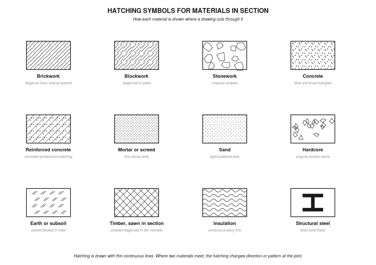
Figure: drawing hatching symbols.
- Brickwork Symbol: Diagonal parallel lines drawn at an even spacing, indicating areas where brick masonry is to be used. It distinguishes brick walls from concrete or block walls.
- Blockwork Symbol: Diagonals drawn in pairs, indicating walls constructed from concrete blocks. This is common in schools and government office buildings due to cost-effectiveness.
- Stonework Symbol: Illustrated as irregular shapes or rough outlines, stonework symbols mark areas where natural or dressed stone masonry is specified, often used in heritage buildings or decorative facades in hotels.
- Concrete Symbol: Represented by a stippled pattern of dots and small triangles, concrete areas like slabs or columns are clearly identified, important in mixed masonry and concrete structural designs.
- Reinforced Concrete Symbol: The concrete stipple with diagonal hatching added, showing where steel reinforcement is embedded, critical in multistorey building projects such as university lecture halls.
- Mortar or Screed: Fine, densely spaced dots, used for bedding joints, renders and floor screeds.
- Hardcore: Angular broken stone shapes, used for the filling beneath ground floor slabs and pavings.
- Earth or Subsoil: Short paired strokes arranged in rows, marking undisturbed ground below foundation level.
- Insulation: A continuous wavy line, used in cavity walls and roofs.
- Structural Steel: Filled solid black, since steel sections are too thin in section to show a pattern.
Rules for hatching:
- Hatching is drawn with thin continuous lines, never thick.
- It is applied only where the cutting plane passes through the material. Anything seen beyond the cut is drawn in outline only.
- Where two different materials meet, the hatching changes pattern or direction at the joint, so the junction is visible.
- Where the same material appears on both sides of a joint, the hatching is drawn in opposite directions to show that they are separate members.
- Large areas may be hatched only around their edges, leaving the middle blank, to keep the drawing readable.
- Every hatching pattern used must appear in the legend on the drawing. Never assume the reader knows it.
1.1.2 Standard Abbreviations in Building Drawings
Abbreviations condense lengthy descriptions into concise forms, facilitating quicker reading and reducing drawing clutter. Understanding these abbreviations is vital for interpreting specifications and instructions accurately.
Materials
- BR: Brick, denotes brick masonry, commonly specified in retail business expansions.
- BLK: Block, indicates concrete block masonry, often used in farm structures due to durability.
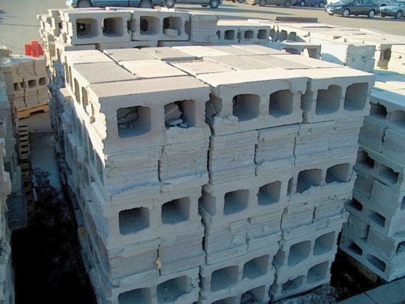
Stack of concrete building blocks (Source: Wikipedia (Concrete block))
- STN: Stone, refers to stone masonry, frequently applied in county government office landscaping walls.
- CONC: Concrete, signifies concrete elements like beams or slabs, standard in hospital construction.
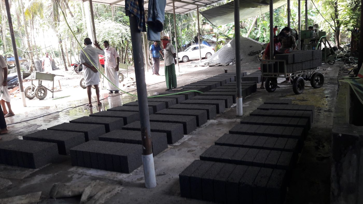
Concrete blocks curing in a shaded area (Source: Wikimedia Commons)
- RC: Reinforced concrete.
- RFT: Reinforced, used to indicate reinforcement, for example reinforced concrete or masonry in multi-storey hotel buildings.
- DPC: Damp proof course.
- DPM: Damp proof membrane.
- HC: Hardcore.
- MS: Mild steel.
- GI: Galvanised iron.
Elements and levels
- FFL: Finished floor level.
- SSL: Structural slab level.
- GL: Ground level.
- DL: Datum level.
- CL: Centre line, shows the exact centre of a wall or feature, essential in precise layout of bank vault walls.
- FDN: Foundation.
- COL: Column.
- BM: Beam.
- LTL: Lintel.
- PLTH: Plinth.
Openings and fittings
- D: Door, usually numbered, as in D1, D2.
- W: Window, usually numbered, as in W1, W2.
- WC: Water closet.
- WHB: Wash hand basin.
- MH: Manhole.
- IC: Inspection chamber.
Drawing notes
- TYP: Typical, marks a recurring detail or element, reducing repetitive notes, important in large cooperative facilities.
- NTS: Not to scale.
- DIA or Ø: Diameter.
- THK: Thickness.
- NO: Number of.
- C/C: Centre to centre, the spacing between repeated members.
- REV: Revision.
- DETAIL: Refers the reader to a larger-scale drawing of that part.
1.1.3 Line Types and Their Meaning
Every line on a drawing carries meaning through two things at once: its pattern, whether continuous, dashed or chained, and its thickness. Two lines with the same pattern but different thickness mean different things.
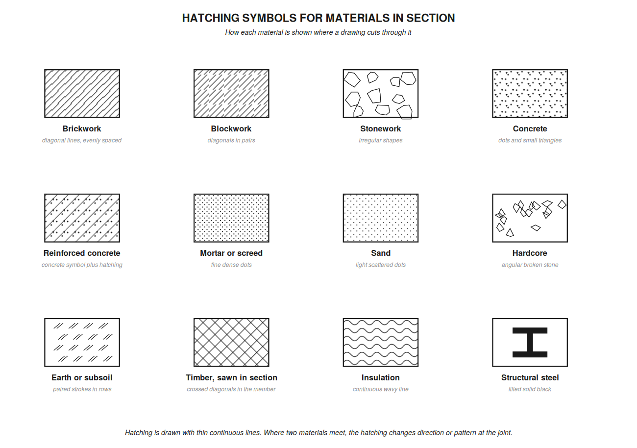
Figure: drawing hatching symbols
- Continuous Thick Line: Represents visible edges and outlines of walls and structural elements. This line type is the most prominent, helping identify the main components of a building such as walls in a TVET college classroom block.
- Continuous Thin Line: Employed for dimension lines, leader lines, and hatching, providing measurements and notes without overwhelming the main drawing, used universally.
- Dashed Line: Indicates hidden or obscured features, such as footing outlines below ground or concealed lintels above openings, which are common in hotel basements.
- Chain Line (long dash followed by a short dash): Used for centre lines or axes, guiding alignment of walls and columns, critical in cooperative warehouse layouts.
- Chain Thin Line Thickened at the Ends: Marks the cutting plane, the position where a section has been taken. Arrows at each end show the direction of view, and letters such as A-A identify which section drawing belongs to it.
- Chain Thick Line: Indicates a surface requiring special treatment or finish.
- Phantom Line (long dash followed by two short dashes): Shows alternate positions or movement paths, less common in masonry but sometimes used in retail store fit-outs for movable partitions, and for parts not included in the contract.
- Break Line (thin continuous zigzag or freehand): Shows that part of the object has been left out, so a long member can be drawn in a short space.
Points to observe:
- A thick line is about twice the width of a thin one. The ratio is kept consistent across the whole drawing.
- Where two line types would coincide, the more important one is drawn: a visible outline takes precedence over a hidden line, and a hidden line over a centre line.
- Dashes in a dashed line start and finish with a dash, not a gap, and meet neatly at corners.
- Centre lines extend a short distance beyond the feature they mark.
1.1.4 Title Blocks and Abbreviation Usage in Drawings
Title blocks are standardized areas on drawings containing project information, revision history, and drawing-specific data. Abbreviations often appear here to summarize complex data succinctly. The title block sits in the bottom right corner of the sheet, where it remains visible when drawings are folded or stacked.
- Project Name: Usually abbreviated for space, for example "CTR HSPTL" for County Referral Hospital, aiding quick identification.
- Client and Consultant: The party commissioning the work and the firm that prepared the drawing.
- Drawing Title: What the sheet shows, such as "Ground Floor Plan" or "Section A-A".
- Drawing Number: A unique code combining letters and numbers, for example "M-02" indicating the second masonry drawing, crucial for document control in large university projects.
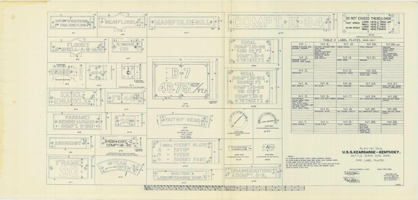
Technical drawing sheet with drawing numbers (Source: Wikimedia Commons)
- Scale: Noted as 1:50 or 1:100, abbreviations here help technicians interpret the drawing size relative to the actual structure, enabling correct measurement conversion. Where more than one scale appears on a sheet, each view carries its own.
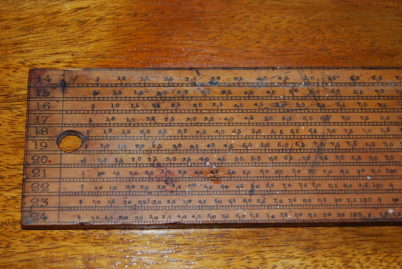
Wooden architect's scale ruler with measurement markings (Source: Wikipedia (Scale ruler))
- Date and Revision: Abbreviated to "Rev" followed by a letter or number, tracking updates to drawings, important in ongoing hotel renovations. Always check the revision before building from a drawing, since an old revision on site is a common and expensive error.
- Drawn By and Checked By: Initials or short names indicate responsible personnel, ensuring accountability in construction of county government offices.
- Units: Usually stated as millimetres, since mixing units on one drawing causes serious errors.
- Notes such as "Do not scale": Where this appears, figured dimensions must be used and nothing may be measured off the sheet.
Practice Questions
- Identify and describe the symbols used for brickwork, blockwork, and stonework in typical building drawings. (10 marks)
- Explain the meaning of the abbreviations BR, BLK, and CONC in masonry drawings and provide an example of where each might be used. (8 marks)
- Differentiate between continuous thick lines and dashed lines in building drawings, citing their significance in interpreting masonry works. (7 marks)
- What information is typically found in a title block, and how do abbreviations aid in its clarity? Provide examples. (10 marks)
The rest of this chapter
🔒Create a free account to open more of this chapter.
Free: practical guides, quick cards, workplace scenarios and more.
Create a free account 🔒1.2 Measurements
Building drawings incorporate various measurement types to convey dimensions and spatial relationships essential for masonry construction. These measurements must be clearly understood to ensure correct material quantities, positioning, and structural integrit…
🔒1.3 Building elevations
Building elevations are essential components of architectural drawings, providing a vertical representation of a building’s exterior. In Kenya’s construction projects, such as county government offices, hospitals, and schools, elevations guide masons and contr…
🔒1.4 Building sections
Building sections are critical components of architectural and structural drawings, providing insight into the internal configuration of a building. In Kenya’s diverse construction projects, from county government offices to hospitality establishments, underst…
Chapter Summary
This chapter focused on interpreting building drawings essential for masonry works. It began by explaining common symbols and abbreviations used in architectural plans, enabling clear communication and understanding among construction professionals. The discussion then moved to measurements, emphasizing how to accurately read and apply dimensions to ensure precise workmanship. Building elevations were covered next, illustrating how these drawings provide a vertical view of the structure’s exterior, detailing heights and finishes. Finally, the chapter examined building sections, which reveal internal details by cutting through the building, showing relationships between different components and construction layers. Mastery of these elements is crucial for correctly executing masonry projects according to design specifications.
Self-Assessment
🔒 PDFDownload this self-assessment, with answers
A. Written Assessment
- What does the symbol of a dashed line typically represent in a masonry building drawing? (2 marks)
- Identify the correct abbreviation for ‘Concrete Block’ commonly used in building drawings. (1 mark)
🔒20 more in this section.
Chapter Examination Questions
🔒 PDFDownload these examination questions, with worked answers
SECTION A (40 Marks) - Answer ALL Questions
- Define the purpose of building drawing symbols and give two examples commonly used in masonry works at a county referral hospital construction site. (4 marks)
- Explain the significance of abbreviations in building drawings and provide three abbreviations related to masonry works. (4 marks)
🔒18 more in this section.
Chapter Practical Activities
Practical 1: Interpret and Explain Common Masonry Symbols and Abbreviations from Building Drawings
Building Technology · Level 5
Masonry Works
PRACTICAL ASSESSMENT
TIME: 4 HOURS
⬇ PDFCandidate Instructions (Candidate Tool)
Type: Individual
INSTRUCTIONS TO CANDIDATE:
1. You are required to perform the following task:
i. Identify and explain the common masonry symbols and abbreviations used in the provided building drawing set of a wall layout measuring 3000mm x 2000mm.
2. You have been provided with the following resources for the practical task:
| Tools & Equipment | Materials |
|---|
| Pencil | Building drawing set with masonry details |
| Eraser | Reference guide for masonry symbols |
| Scale ruler | |
| Notebook | |
⬇ PDFResources Required (Cutting List)
| S/N | Item | Quantity |
|---|
| 1 | Building drawing set with masonry details | 1 set per candidate |
| 2 | Pencil | 1 pc per candidate |
| 3 | Eraser | 1 pc per candidate |
| 4 | Scale ruler (metric) | 1 pc per candidate |
| 5 | Notebook or writing pad | 1 pc per candidate |
| 6 | Reference guide for masonry symbols | 1 copy per candidate |
⬇ PDFAssessor Guide
| Items to be Evaluated | Marks Available | Marks Obtained | Comments |
|---|
| TASK 1: PPE and Preparation |
Wore PPEs as per site safety standards (dustcoat, safety boots)
(Award 1 mark each for correctly worn PPE) | 2 | | |
Assembled and used necessary tools (pencil, eraser, scale ruler, notebook)
(Award 1 mark each for each tool used correctly) | 3 | | |
Prepared working area by organizing drawing and reference materials
(Award 1 mark for neat and organized setup) | 1 | | |
| Sub-Total | 6 | | |
| TASK 2: Identification and Interpretation of Symbols and Abbreviations |
Correctly identified at least five common masonry symbols from the drawing
(Award 1 mark for each correctly identified symbol x 5 = 5 Marks) | 5 | | |
Correctly identified at least five standard abbreviations used in masonry drawings
(Award 1 mark for each correctly identified abbreviation x 5 = 5 Marks) | 5 | | |
Explained the meaning and application of each identified symbol and abbreviation
(Award 1 mark for each accurate explanation x 6 = 6 Marks) | 6 | | |
| Sub-Total | 16 | | |
| PRODUCT CHECKLIST |
Accurate interpretation of symbols and abbreviations as per standard masonry practice
(Award up to 5 marks for correct and complete interpretation) | 5 | | |
Neatness and clarity of notes and explanations in the notebook
(Award up to 3 marks for legible and well-organized notes) | 3 | | |
Correct referencing of symbols to drawing locations
(Award 1 mark for each correct reference x 4 = 4 Marks) | 4 | | |
| Sub-Total | 12 | | |
| GRAND TOTAL | 34 | | |
ASSESSMENT OUTCOME: ☐ Competent ☐ Not Yet Competent (competent if at least 50%)
Practical 2: Measure and scale dimensions from a building drawing
Building Technology · Level 5
Masonry Works
PRACTICAL ASSESSMENT
TIME: 4 HOURS
⬇ PDFCandidate Instructions (Candidate Tool)
Type: Individual
INSTRUCTIONS TO CANDIDATE:
1. You are required to perform the following task:
i. Measure and convert all key dimensions from the provided 1:100 scale building drawing to actual site dimensions in millimeters.
2. You have been provided with the following resources for the practical task:
| Tools & Equipment | Materials |
|---|
| Tape Measure (5 m) | Building Drawing (Scale 1:100) |
| Scale Ruler (Architectural scale) | Field Book |
| Pencil | |
| Eraser | |
| Calculator | |
⬇ PDFResources Required (Cutting List)
| S/N | Item | Quantity |
|---|
| 1 | Tape Measure (5 m) | 1 Pc per Candidate |
| 2 | Scale Ruler (Architectural scale) | 1 Pc per Candidate |
| 3 | Pencil | 1 Pc per Candidate |
| 4 | Eraser | 1 Pc per Candidate |
| 5 | Calculator | 1 Pc per Candidate |
| 6 | Building Drawing (Scale 1:100) | 1 Pc per Candidate |
| 7 | Field Book | 1 Pc per Candidate |
| 8 | Safety Boots | 1 Pair per Candidate |
| 9 | Dust Coat/Overall | 1 Pc per Candidate |
| 10 | Gloves | 1 Pair per Candidate |
⬇ PDFAssessor Guide
| Items to be Evaluated | Marks Available | Marks Obtained | Comments |
|---|
| TASK 1: Preparation and PPE |
Wore PPE appropriately (Dust coat, Safety boots, Gloves)
(Award 1 mark each for correct PPE donned = 3 Marks) | 3 | | |
Cleared and prepared workspace
(Award 2 marks for cleared and organized workspace) | 2 | | |
Assembled required tools and materials
(Award 2 marks for having all tools/materials ready) | 2 | | |
| Sub-Total | 7 | | |
| TASK 2: Measurement and Scaling |
Correctly identified scale on the drawing
(Award 3 marks for accurate identification of 1:100 scale) | 3 | | |
Accurately measured length dimensions on drawing using scale ruler
(Award 1 mark each for 5 correct length measurements) | 5 | | |
Accurately measured width dimensions on drawing using scale ruler
(Award 1 mark each for 5 correct width measurements) | 5 | | |
Converted measured dimensions to actual site dimensions correctly
(Award 1 mark each for 8 correct conversions) | 8 | | |
Recorded all measurements and conversions neatly in field book
(Award 2 marks for complete and legible recording) | 2 | | |
| Sub-Total | 23 | | |
| PRODUCT CHECKLIST |
Correct actual site length dimension: 15000 mm
(Award 3 marks for correct length dimension) | 3 | | |
Correct actual site width dimension: 9000 mm
(Award 3 marks for correct width dimension) | 3 | | |
Correct actual site height dimension: 3000 mm
(Award 3 marks for correct height dimension) | 3 | | |
All converted dimensions consistent with 1:100 scale
(Award 4 marks for consistent scaling across all dimensions) | 4 | | |
Neatness and completeness of recorded data
(Award 4 marks for neat, complete, and legible data) | 4 | | |
| Sub-Total | 17 | | |
| GRAND TOTAL | 47 | | |
ASSESSMENT OUTCOME: ☐ Competent ☐ Not Yet Competent (competent if at least 50%)
🔒Prepare a materials list from building drawing measurements for a masonry wallPractical 3
🔒Interpret Building Elevation Drawings for Wall Heights and OpeningsPractical 4
🔒Marking out masonry wall layout on site using elevation dataPractical 5
🔒Interpret building section drawings for wall thicknesses, floor levels, and foundation depthsPractical 6
🔒Draw a simple masonry wall section with dimensionsPractical 7
🔒Compare symbols and abbreviations on building elevation and section drawingsPractical 8
🔒Calculate Wall Area from Elevation Drawings for Plastering EstimationPractical 9
🔒Interpret cross-sectional building drawings to identify masonry joint typesPractical 10
