Fluid pumps are essential components in automotive engineering, responsible for moving liquids such as coolant, fuel, and lubricants through various vehicle systems. Mastering the operation of different types of pumps enhances the ability of automotive technicians to maintain engine efficiency and prevent system failures. This chapter focuses on the principles of operation of reciprocating and centrifugal pumps, which are commonly used in vehicles and automotive workshops in Kenya. Understanding these fundamentals equips professionals to diagnose pump-related issues and ensure optimal fluid flow in automotive systems.
10.1 Principles of operation of
10.1.1 Reciprocating pumps
Reciprocating pumps operate by converting the reciprocating motion of a piston or plunger into fluid flow, making them suitable for applications requiring high pressure and precise fluid delivery. In automotive engineering, these pumps are often found in fuel injection systems and lubrication circuits where controlled flow rates are critical. Their design allows for positive displacement, meaning a fixed amount of fluid is moved with each piston stroke, which is particularly valuable in systems demanding consistent pressure and volume.
Construction and Main Components of Reciprocating Pumps
The construction of reciprocating pumps involves several key components that work in unison to create fluid flow:
- Cylinder: Acts as the chamber where the piston moves back and forth to displace fluid.
- Piston or Plunger: Moves reciprocally within the cylinder to create suction and discharge strokes.
- Inlet and Outlet Valves: Control the flow of fluid into and out of the cylinder, ensuring unidirectional flow.
- Crankshaft and Connecting Rod: Convert rotary motion from the engine or motor into the reciprocating motion of the piston.
- Pump Casing: Encloses the components and maintains fluid pressure while preventing leaks.
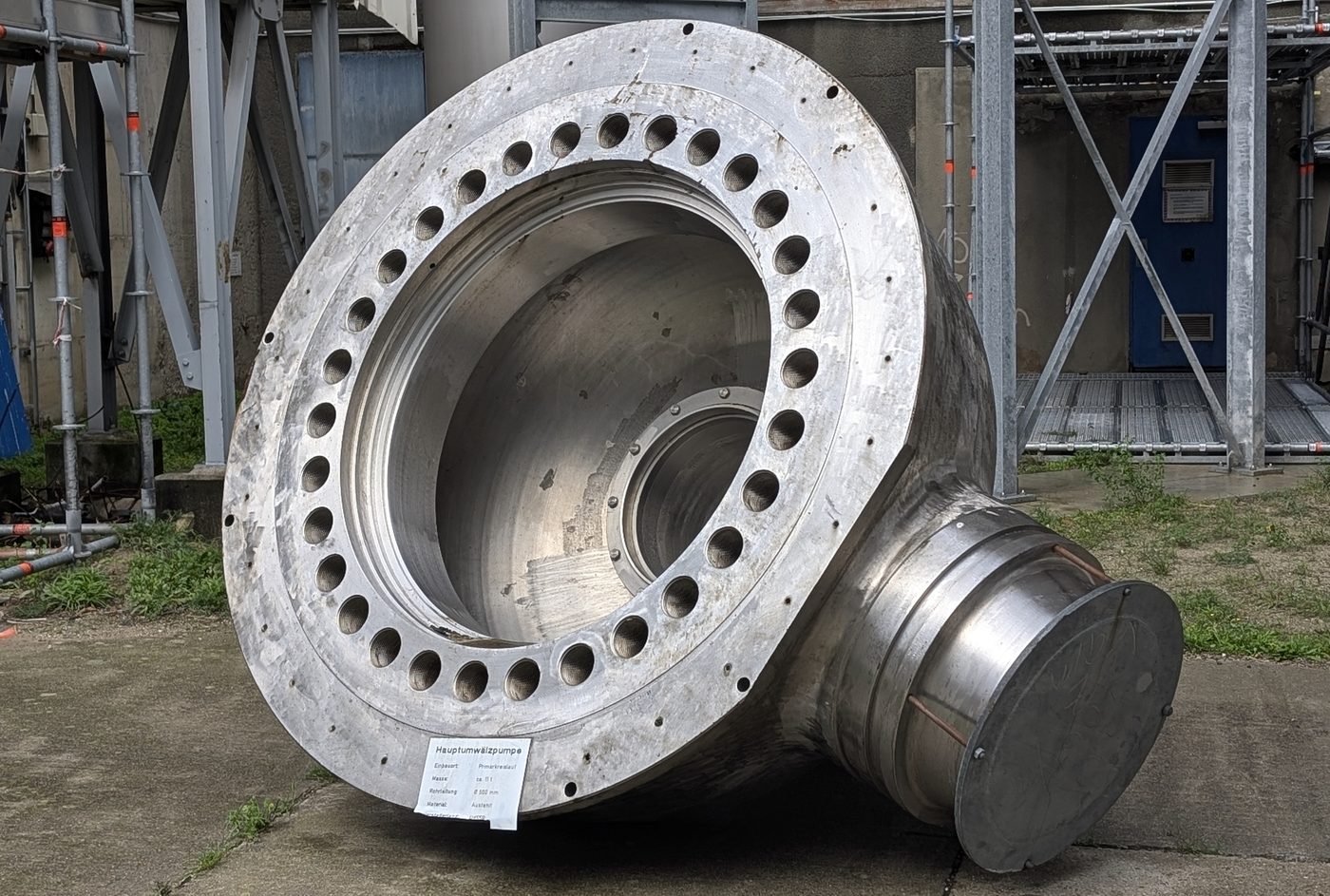
Large metal pump casing component (Source: Wikimedia Commons)
Each component must be precisely machined to ensure tight seals and efficient operation, which is critical in automotive fuel pumps to prevent leaks and maintain pressure.
Operating Principle and Cycle Phases
The reciprocating pump operates through a two-phase cycle: suction and delivery.
- Suction Stroke: The piston moves away from the cylinder head, increasing the volume inside the cylinder and creating a vacuum. This vacuum causes the inlet valve to open, allowing fluid to enter the cylinder from the supply line.
- Delivery Stroke: The piston moves towards the cylinder head, decreasing the volume and increasing pressure inside the cylinder. The inlet valve closes due to the pressure rise, and the outlet valve opens, forcing fluid into the delivery pipe or system.
This cycle repeats continuously, generating a steady flow of fluid. In automotive lubrication systems, for instance, this ensures oil reaches various engine parts with the required pressure.
Characteristics and Performance Factors
Reciprocating pumps exhibit several performance characteristics influenced by design and operating conditions:
- Positive Displacement: Delivers a fixed volume per stroke, resulting in high pressure capability and precise flow control.
- Pulsating Flow: The flow is not continuous but occurs in pulses corresponding to piston strokes, which may require dampeners in sensitive systems.
- High Efficiency at Low Speeds: Effective in automotive systems where low-speed operation is common, such as in fuel injection pumps.
- Pressure Limitations: Can generate very high pressures but are limited by the strength of components and valve design.
- Maintenance Requirements: Periodic inspection of valves and piston seals is necessary to prevent leakage and maintain efficiency.
Applications in Automotive Engineering
In Kenya's automotive sector, reciprocating pumps are primarily used in:
- Diesel Fuel Injection Systems: Delivering fuel at high pressure to injectors for efficient combustion in vehicles such as matatus and trucks.
- Lubrication Systems: Circulating engine oil to critical components, ensuring smooth operation and reducing wear.
- Hydraulic Brake Systems: Some older or specialized brake systems use reciprocating pumps to maintain hydraulic pressure.
- Cooling Systems: In certain engine designs, these pumps circulate coolant within tight pressure tolerances.
- Transmission Fluid Circulation: Maintaining pressure in automatic transmission systems for smooth gear changes.
Understanding the operational principles helps automotive engineers troubleshoot pump failures and optimize system performance.
10.1.2 Centrifugal pumps
Centrifugal pumps are widely used in automotive applications for their ability to handle large volumes of fluid at moderate pressures with smooth, continuous flow. Unlike reciprocating pumps, they rely on rotational kinetic energy to move fluid, making them ideal for cooling systems and water pumps in vehicles. Their simple design and fewer moving parts contribute to lower maintenance costs and higher reliability in everyday automotive use.
Construction and Key Components of Centrifugal Pumps
Centrifugal pumps consist of several fundamental parts that enable their operation:
| Name |
Specification |
Use |
| Impeller |
Usually made of cast iron or stainless steel with curved vanes |
Converts rotational energy into fluid velocity |
| Pump Casing |
Volute or diffuser-shaped casing made from cast iron or aluminium |
Directs fluid flow and converts velocity to pressure |
| Shaft |
Steel shaft connected to the impeller |
Transmits power from the motor or engine to the impeller |
| Bearings |
Ball or roller bearings supporting the shaft |
Ensure smooth rotation and reduce friction |
| Mechanical Seal |
Carbon or ceramic seal around the shaft |
Prevents fluid leakage along the shaft |
The impeller's design and the casing shape determine the pump’s efficiency and the pressure it can generate, critical for automotive cooling systems to maintain optimal engine temperature.
Operating Principle and Fluid Movement
Centrifugal pumps operate based on the principle of centrifugal force generated by the rotating impeller:
- Fluid enters the pump through the eye of the impeller at low velocity.
- The impeller blades impart kinetic energy to the fluid, causing it to accelerate radially outward.
- As the fluid exits the impeller, it enters the volute casing where the high velocity is converted into pressure energy.
- The pressurized fluid is then discharged into the system, such as the radiator circuit in an automobile.
This continuous flow is smooth and steady, making centrifugal pumps suitable for cooling and water circulation in automotive applications.
Performance Characteristics and Operating Parameters
The performance of centrifugal pumps is influenced by several factors relevant to automotive engineering:
- Flow Rate: Typically high, suitable for circulating large volumes of coolant or water.
- Pressure Head: Moderate pressure generation, sufficient for radiator circuits but less than reciprocating pumps.
- Efficiency: Depends on impeller design and pump speed; well-maintained pumps in vehicles can achieve efficiencies above 70%.
- Cavitation Sensitivity: Occurs if the pump inlet pressure drops below vapor pressure, causing damage; proper system design in vehicle cooling circuits prevents this.
- Operating Speed: Usually proportional to engine speed; variable-speed pumps adjust flow according to cooling demand.
These parameters must be considered when selecting and maintaining pumps in automotive fluid systems to ensure reliable operation.
Applications in Automotive Engineering
Centrifugal pumps are integral to various automotive systems in Kenya’s vehicle maintenance and manufacturing sectors:
- Engine Cooling Systems: Circulate coolant through the engine block and radiator, preventing overheating in vehicles ranging from private cars to public service vehicles.
- Windshield Washer Systems: Provide steady fluid flow to clean the windshield.
- Fuel Transfer Pumps: In some cases, centrifugal pumps are used for transferring fuel between tanks or to the engine.
- Air Conditioning Systems: Circulate refrigerant or cooling fluids in vehicle HVAC systems.
- Water Pumps in Workshops: Used in automotive repair workshops for fluid transfer and testing cooling systems.
The simplicity and reliability of centrifugal pumps make them a preferred choice for continuous fluid flow applications in automotive engineering.
Practice Questions
- Explain the working principle of a reciprocating pump and describe its typical applications in automotive engineering. (10 marks)
- Compare the construction and operation of reciprocating and centrifugal pumps used in automotive fluid systems. (15 marks)
- What are the main factors affecting the performance of centrifugal pumps in vehicle cooling systems? (10 marks)
- Detail the components of a reciprocating pump and explain the function of each in the context of fuel delivery. (10 marks)
- Describe how cavitation occurs in centrifugal pumps and its impact on automotive pump performance. (10 marks)
The rest of this chapter
🔒Create a free account to open more of this chapter.
Free: practical guides, quick cards, workplace scenarios and more.
Create a free account 🔒10.2 Derivation of Equations for a Reciprocating Pump
Understanding the derivation of key equations for reciprocating pumps is fundamental for automotive engineering professionals in Kenya who work with fluid systems in vehicle maintenance and repair. Reciprocating pumps are commonly used to transfer fluids in au…
🔒10.3 Application of Reciprocating Pumps Equations to Solve Problems
In the Kenyan automotive engineering sector, understanding and applying reciprocating pump equations is essential for diagnosing, designing, and maintaining fluid systems in vehicles and workshop equipment. Reciprocating pumps, widely used in automotive worksh…
🔒10.4 Derivation of Equations for a Centrifugal Pump
In automotive engineering technology, understanding the derivation of equations for centrifugal pumps is vital for selecting, operating, and troubleshooting these pumps in vehicle cooling systems, lubrication circuits, and fuel delivery mechanisms. Centrifugal…
🔒10.5 Application of Centrifugal Pump Equations to Solve Problems
In the Kenyan automotive engineering industry, understanding and applying centrifugal pump equations is essential for diagnosing and optimizing fluid systems such as cooling systems, fuel delivery, and lubrication circuits. Skilled technicians and engineers mu…
Chapter Summary
This chapter explored the fundamental principles behind the operation of fluid pumps, focusing on reciprocating and centrifugal pumps. It detailed how reciprocating pumps function through their back-and-forth motion to move fluid, while centrifugal pumps use rotational motion to impart velocity and pressure to the fluid. The chapter then derived key equations for reciprocating pumps, explaining important concepts such as coefficient of discharge, percentage slip, work done, acceleration head, friction head, and pressure head within the cylinder. These equations were applied to solve practical problems, reinforcing theoretical understanding. Similarly, equations for centrifugal pumps were derived, covering effective head, manometric head, overall efficiency, mechanical efficiency, discharge, torque, work done per unit weight, and specific speed. The application of these centrifugal pump equations to problem-solving was also thoroughly examined. This comprehensive approach provided a solid foundation for analyzing and operating both types of pumps in various engineering contexts.
Self-Assessment
🔒 PDFDownload this self-assessment, with answers
A. Written Assessment
- What is the primary difference in the operating principle between a reciprocating pump and a centrifugal pump? (2 marks)
- Define the term "coefficient of discharge" in the context of a reciprocating pump and explain its significance. (3 marks)
🔒20 more in this section.
Chapter Examination Questions
🔒 PDFDownload these examination questions, with worked answers
SECTION A (40 Marks) - Answer ALL Questions
- Differentiate between the working principles of a reciprocating pump and a centrifugal pump used in automotive cooling systems. (4 marks)
- Explain the role of the coefficient of discharge in evaluating the performance of a reciprocating pump in fuel injection systems. (4 marks)
🔒18 more in this section.
