4.1 Fundamentals of Orthographic Projection
Orthographic projection is a core technique in automotive design and engineering, enabling technicians to represent three-dimensional components in two dimensions accurately. This section introduces the foundational concepts and clarifies how orthographic drawings differ from other common drawing types used in automotive technology.
4.1.1 Definition and Importance of Orthographic Drawing
Orthographic drawing is a method of representing a three-dimensional object using several two-dimensional views, typically the front, top, and side, projected orthogonally onto planes. This technique is essential in automotive engineering because it allows for unambiguous interpretation of component shapes and dimensions necessary for manufacturing and quality control.
- Clear Visualization of Complex Shapes: Orthographic drawings break down complex automotive parts into simple views, making it easier for technicians to understand intricate geometries.
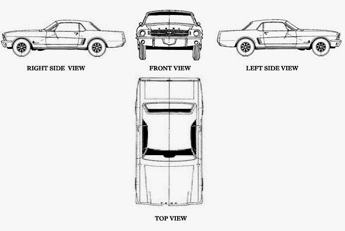
Four orthographic views of a car (Source: 697c72e40165f702)
- Standardized Communication: They provide a universal language for engineers, technicians, and fabricators, minimizing errors caused by misinterpretation.
- Accurate Dimensioning: Orthographic views enable precise measurement of length, width, height, and other critical dimensions, which is vital for ensuring parts fit and function correctly.
- Documentation for Manufacturing: These drawings serve as official records and references during fabrication, assembly, and maintenance of automotive systems.
- Quality Assurance: Orthographic drawings support inspection and verification processes by providing exact specifications against which manufactured parts are checked.
4.1.2 Differences between Orthographic and Other Drawing Types (Isometric, Perspective)
Understanding how orthographic projection contrasts with isometric and perspective drawings is important for automotive professionals who must choose the appropriate drawing type for various stages of design and communication.
- Dimensional Representation: Orthographic drawings represent objects using multiple flat views without distortion, whereas isometric drawings present a single view showing three dimensions equally foreshortened, and perspective drawings mimic human eye perception with vanishing points.
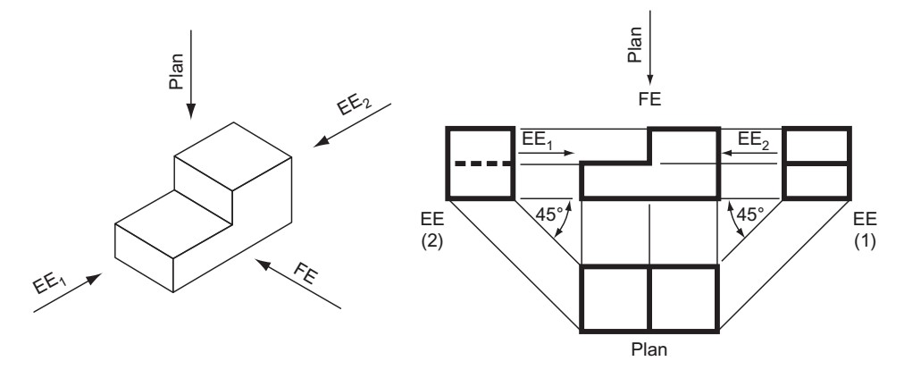
An isometric view and its corresponding orthographic projections (fron (Source: PLUMB 5 LEARNING GUIDE-1 (1))
- Purpose and Use: Orthographic drawings are used for precise manufacturing and inspection, isometric drawings for conceptual visualization and quick spatial understanding, and perspective drawings mainly for presentations and marketing.
- Scale and Measurement: Orthographic views maintain true dimensions and scale, allowing direct measurement from the drawing, unlike perspective drawings where scale varies with depth.
- Complexity of Interpretation: Orthographic drawings require understanding multiple views to visualize the complete object, whereas isometric and perspective drawings offer a more intuitive single-view representation.
- Standardization: Orthographic projection follows strict engineering standards (BS EN ISO 5456) for layout and symbols, while isometric and perspective drawings have less rigid conventions.
4.1.3 Projection Planes and Views in Orthographic Drawing
Orthographic projection involves projecting the features of an object onto perpendicular planes to create views that represent different sides of the object.
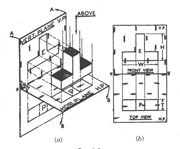
A 3D isometric view and corresponding orthographic projections (front (Source: 697c72e40165f702)
- Principal Planes: The three main planes are the frontal (front view), horizontal (top view), and profile (side view), each perpendicular to the others.
- Front View: Shows the height and width of the object; it is usually the most descriptive view.
-
Top View: Displays the width and depth, providing details not visible in the front view.
-
Side View: Reveals the height and depth, completing the spatial understanding of the object.
- Auxiliary Views: Used when features are inclined or oblique and cannot be accurately represented by principal views.
4.1.4 Importance of Scale and Line Conventions in Orthographic Drawing
Applying correct scale and line types is vital for clarity and adherence to engineering standards, ensuring drawings are interpreted correctly in automotive workshops.
- Scale Selection: Choosing an appropriate scale (e.g., 1:1, 1:2, 2:1) balances detail visibility with drawing size constraints.
- Visible Lines: Thick continuous lines represent edges visible to the observer.
- Hidden Lines: Thin dashed lines indicate edges obscured from view.
- Centre Lines: Thin alternating long and short dashes mark symmetry axes and centre points.
- Dimension Lines and Extension Lines: Thin solid lines with arrowheads and extension marks define the size and location of features precisely.
Practice Questions
- Explain why orthographic drawings are preferred for manufacturing automotive parts over isometric drawings. (10 marks)
- List five key differences between orthographic and perspective drawings in automotive engineering. (10 marks)
- Describe the role of the front, top, and side views in orthographic projection with respect to an automotive engine component. (15 marks)
- Identify and explain the significance of at least four different line types used in orthographic drawings. (10 marks)
The rest of this chapter
🔒Create a free account to open more of this chapter.
Free: practical guides, quick cards, workplace scenarios and more.
Create a free account 🔒4.2 Types of Orthographic Projections
Different orthographic projection methods are employed depending on regional standards and industry practices. This section focuses on the first-angle and third-angle projection methods, both relevant to automotive engineering drawing in Kenya. First-angle pro…
🔒4.3 Understanding Views
In automotive engineering technology, producing accurate orthographic drawings is fundamental for communicating complex component designs. Orthographic views allow engineers and technicians in Kenyan automotive workshops, manufacturing plants, and maintenance…
🔒4.4 First Angle Orthographic Drawings
For automotive engineering drawings in Kenya, the first angle projection method is the standard, conforming to ISO and BS conventions. Developing first-angle orthographic drawings requires strict adherence to layout rules, symbol usage, and dimensioning standa…
🔒4.5 Third Angle Orthographic Drawings
In Automotive Engineering Technology in Kenya, third angle orthographic projection is the standard drawing method used for representing automotive parts and assemblies. This method ensures clear communication between design engineers, manufacturers, and techni…
🔒4.6 Saving Orthographic Drawings
In the automotive engineering sector in Kenya, properly saving orthographic drawings is critical to maintaining version control, ensuring data integrity, and facilitating easy retrieval during manufacturing and maintenance. Digital CAD files must be saved usin…
🔒4.7 Dimensioning Orthographic Views
Dimensioning orthographic views is a critical skill in automotive engineering technology, enabling precise communication of component sizes and relationships for manufacturing and quality control. In Kenya’s automotive workshops and parts manufacturing units,…
🔒4.8 Printing Orthographic Views
Printing orthographic views is the final step in producing technical drawings for automotive engineering projects. Proper printing ensures that drawings are clear, correctly scaled, and usable on the workshop floor or in client presentations. In Kenya’s automo…
🔒4.9 Creating isometric drawing
In automotive engineering technology, creating isometric drawings is essential for visualizing complex automotive components and assemblies in three dimensions on a two-dimensional surface. Isometric drawings facilitate clearer communication among engineers, t…
🔒4.10 Creating 3D Model
In the automotive engineering sector in Kenya, creating accurate 3D models is essential for designing vehicle components, assemblies, and systems before physical prototyping. These models facilitate better visualization, interference checking, and communicatio…
Chapter Summary
This chapter explored the fundamentals of orthographic projection, emphasizing its definition and significance compared to other drawing types such as isometric and perspective drawings. It detailed the two main types of orthographic projections: first-angle and third-angle, explaining their distinct conventions. The chapter then covered the essential views used in orthographic drawings, including front, top, and side views, as well as additional sectional and auxiliary views. Step-by-step procedures for producing both first-angle and third-angle orthographic drawings following standard practices were presented. Techniques for saving and printing orthographic drawings were also discussed to ensure proper documentation and presentation. The chapter further introduced the creation of isometric drawings, focusing on selecting the isometric cursor, dimensioning, and printing these views. Finally, it addressed the process of creating 3D models within a CAD environment, highlighting workspace selection, modification tools, rendering, and printing of 3D models.
Self-Assessment
🔒 PDFDownload this self-assessment, with answers
A. Written Assessment
- What is the primary purpose of orthographic projection in automotive engineering design? (2 marks)
- Differentiate between first-angle and third-angle projection with respect to the position of the views. (3 marks)
🔒20 more in this section.
Chapter Examination Questions
🔒 PDFDownload these examination questions, with worked answers
SECTION A (40 Marks) - Answer ALL Questions
- Define orthographic projection and explain its importance in automotive engineering drawing. (4 marks)
- Differentiate between first-angle and third-angle orthographic projection methods. (4 marks)
🔒18 more in this section.
Chapter Practical Activities
Practical 1: Explain fundamentals and importance of orthographic projection
Automotive Engineering Technology · Level 6
Computer Aided Drawing
PRACTICAL ASSESSMENT
TIME: 4 HOURS
⬇ PDFCandidate Instructions (Candidate Tool)
Type: Individual
INSTRUCTIONS TO CANDIDATE:
1. You are required to perform the following task:
i. Annotate and explain the fundamentals and importance of orthographic projection on an A2 sheet showing front, top and side views of a 150mm x 100mm x 80mm rectangular block.
2. You have been provided with the following resources for the practical task:
| Tools & Equipment | Materials |
|---|
| T-square | A2 Drawing paper |
| Engineering set | Printing Papers |
| Assorted pencils: 2H, 4H and HB | Rewritable CD |
| Eraser and Masking tape | |
| Set squares | |
⬇ PDFResources Required (Cutting List)
| S/N | Item | Quantity |
|---|
| 1 | A2 Drawing paper | 1 Pc per Candidate |
| 2 | Rewritable CD | 1 Pc per Candidate |
| 3 | Computer installed with AutoCAD | 1 Pc per Candidate |
| 4 | Printing Papers | Sufficient |
| 5 | Drawing Table | 1 Pc per Candidate |
| 6 | T-square | 1 Pc per Candidate |
| 7 | Engineering set | 1 Pc per Candidate |
| 8 | Assorted pencils: 2H, 4H and HB | 1 Pc each per Candidate Total 3 Pcs |
| 9 | Eraser and Masking tape | 1 Pc per Candidate |
| 10 | Set squares | 1 Pair per Candidate |
⬇ PDFAssessor Guide
| Items to be Evaluated | Marks Available | Marks Obtained | Comments |
|---|
| TASK 1: Demonstrate understanding of orthographic projection fundamentals |
Wore appropriate personal protective equipment (e.g. overcoat, safety boots if applicable)
(Award 1 mark for correct PPE worn or zero) | 1 | | |
Set up drawing workspace correctly with all tools and materials arranged
(Award 2 marks for proper setup or zero) | 2 | | |
Selected and used correct drawing tools (T-square, set squares, pencils) appropriately
(Award 2 marks for correct tool usage or zero) | 2 | | |
Produced orthographic views (front, top, side) of the rectangular block accurately
(Award 5 marks for accuracy or zero) | 5 | | |
Annotated the drawing with correct fundamentals of orthographic projection
(Award 4 marks for clear, correct annotations or zero) | 4 | | |
Explained the importance of orthographic projection in technical drawing clearly
(Award 3 marks for clear explanation or zero) | 3 | | |
Highlighted differences between orthographic projection and other drawing types (isometric, perspective)
(Award 3 marks for correct differentiation or zero) | 3 | | |
| Sub-Total | 20 | | |
| PRODUCT CHECKLIST |
Orthographic drawings show front, top and side views with dimensions 150mm x 100mm x 80mm accurately represented
(Award 6 marks for correct dimensions and views or zero) | 6 | | |
Annotations correctly describe fundamentals such as projection planes, viewing directions, and true shape representation
(Award 4 marks for correct annotations or zero) | 4 | | |
Explanation clearly states importance of orthographic drawings in communication and manufacturing
(Award 5 marks for clear, relevant explanation or zero) | 5 | | |
Differences between orthographic, isometric, and perspective drawings are correctly identified and explained
(Award 5 marks for accurate differences or zero) | 5 | | |
| Sub-Total | 20 | | |
| GRAND TOTAL | 40 | | |
ASSESSMENT OUTCOME: ☐ Competent ☐ Not Yet Competent (competent if at least 50%)
Practical 2: Identify and Differentiate First-Angle and Third-Angle Orthographic Projections
Automotive Engineering Technology · Level 6
Computer Aided Drawing
PRACTICAL ASSESSMENT
TIME: 4 HOURS
⬇ PDFCandidate Instructions (Candidate Tool)
Type: Individual
INSTRUCTIONS TO CANDIDATE:
1. You are required to perform the following task:
i. Select and label first-angle and third-angle projection types on 300mm x 200mm orthographic sample drawings and explain their projection conventions clearly.
2. You have been provided with the following resources for the practical task:
| Tools & Equipment | Materials |
|---|
| Computer installed with AutoCAD | A2 Drawing Paper |
| Drawing Table | Rewritable CD |
| T-square | Printing Papers |
| Engineering Set | |
| Assorted Pencils: 2H, 4H, HB | |
| Eraser and Masking Tape | |
| Set Squares | |
⬇ PDFResources Required (Cutting List)
| S/N | Item | Quantity |
|---|
| 1 | A2 Drawing Paper | 1 Pc per Candidate |
| 2 | Rewritable CD | 1 Pc per Candidate |
| 3 | Computer installed with AutoCAD | 1 Pc per Candidate |
| 4 | Printing Papers | Sufficient |
| 5 | Drawing Table | 1 Pc per Candidate |
| 6 | T-square | 1 Pc per Candidate |
| 7 | Engineering Set | 1 Pc per Candidate |
| 8 | Assorted Pencils: 2H, 4H, HB | 1 Pc each per Candidate |
| 9 | Eraser and Masking Tape | 1 Pc per Candidate |
| 10 | Set Squares | 1 Pair per Candidate |
⬇ PDFAssessor Guide
| Items to be Evaluated | Marks Available | Marks Obtained | Comments |
|---|
| TASK 1: Identification and Annotation of Projection Types |
Wore appropriate personal protective equipment (overall, safety boots)
(Award 1 mark for each PPE worn correctly or zero) | 2 | | |
Set up the working area with necessary tools and materials
(Award 1/2 mark for each tool/material arranged properly) | 3 | | |
Opened and loaded sample orthographic drawings in AutoCAD
(Award 3 marks for correct and timely loading or zero) | 3 | | |
Correctly identified first-angle projection drawing
(Award 5 marks for correct identification with justification or zero) | 5 | | |
Correctly identified third-angle projection drawing
(Award 5 marks for correct identification with justification or zero) | 5 | | |
Accurately labeled projection symbols and views on drawings
(Award 1 mark per correct label or zero) | 6 | | |
Explained projection conventions clearly in writing or verbal form
(Award marks based on clarity and completeness of explanation) | 6 | | |
| Sub-Total | 30 | | |
| PRODUCT CHECKLIST |
Projection types correctly selected and labeled on 300mm x 200mm drawings
(Award 10 marks for accurate labeling and dimension compliance or zero) | 10 | | |
Projection conventions explanation is clear, concise, and technically accurate
(Award 10 marks for completeness and correctness or zero) | 10 | | |
| Sub-Total | 20 | | |
| GRAND TOTAL | 50 | | |
ASSESSMENT OUTCOME: ☐ Competent ☐ Not Yet Competent (competent if at least 50%)
🔒Produce Orthographic Drawings of a Machine ComponentPractical 3
🔒Create Sectional and Auxiliary Views from Orthographic DrawingPractical 4
🔒Produce first-angle orthographic drawing of a mechanical bracketPractical 5
🔒Create Third-Angle Orthographic Drawing of Mechanical ComponentPractical 6
🔒Apply Dimensioning Techniques on Orthographic ViewsPractical 7
🔒Save orthographic drawings using proper file managementPractical 8
🔒Print Orthographic Views with Correct Scale and SettingsPractical 9
🔒Create an isometric drawing of a mechanical component using isometric cursorPractical 10
🔒Dimension an isometric drawing accuratelyPractical 11
🔒Print an isometric drawing with correct scale and layoutPractical 12
🔒Build a 3D CAD Model of a Mechanical ComponentPractical 13
🔒Modify a 3D Mechanical Part Model Using 3D Editing ToolsPractical 14
🔒Render and print a shaded orthographic projection of a 3D mechanical partPractical 15
