
By the end of this chapter, you will be able to:
Mastering these skills helps you work confidently and safely with electrical systems, which is essential for success in the electrical trade.
Electrical and electronic systems are fundamental in modern automotive engineering, as vehicles increasingly rely on electrical components for operation, safety, and comfort. Understanding the basic electrical quantities and units is essential for diagnosing, repairing, and designing automotive electrical circuits. This chapter introduces the foundational concepts of electrical measurements and materials, focusing on how these principles apply to automotive technology in Kenya. Mastery of these concepts equips automotive engineers and technicians to work effectively with vehicle electrical systems, enhancing performance and safety.
The International System of Units (SI) provides a standardized framework for measuring physical quantities, including those relevant to electrical engineering. In the Kenyan automotive industry, adherence to SI units ensures consistency in vehicle diagnostics, repair, and communication with global automotive standards. This section explores the fundamental SI units used to quantify electrical phenomena essential for automotive electrical system analysis.
The SI system defines seven base units from which all other units are derived. For automotive electrical applications, the key units include the ampere for electric current, the volt for electric potential, and the ohm for resistance. These units ensure precise measurement and interpretation of electrical parameters in vehicle systems.
Power is the rate at which electrical energy is converted into another form such as light, heat or motion, and its SI unit is the watt (W). One watt is one joule of energy per second. It is calculated as voltage multiplied by current, and it is used to rate automotive electrical devices such as headlights and heating elements. Example: a county government garage rates a 12 V headlamp bulb at 55 W, so a technician can work out how much current it draws and choose a correctly rated fuse.
Formula: power = voltage × current
Substitution: power = 12 V × 4.58 A
Working: 12 × 4.58 = 54.96
Result: power ≈ 55 W
Current is the flow rate of electric charge through a conductor, and its SI unit is the ampere (A). One ampere is one coulomb of charge passing a point each second. It is critical for assessing current in vehicle wiring and components like alternators and starter motors. Example: a school bus workshop finds that a starter motor draws 200 A when cranking, which explains why the battery cables must be thick and the connections clean.
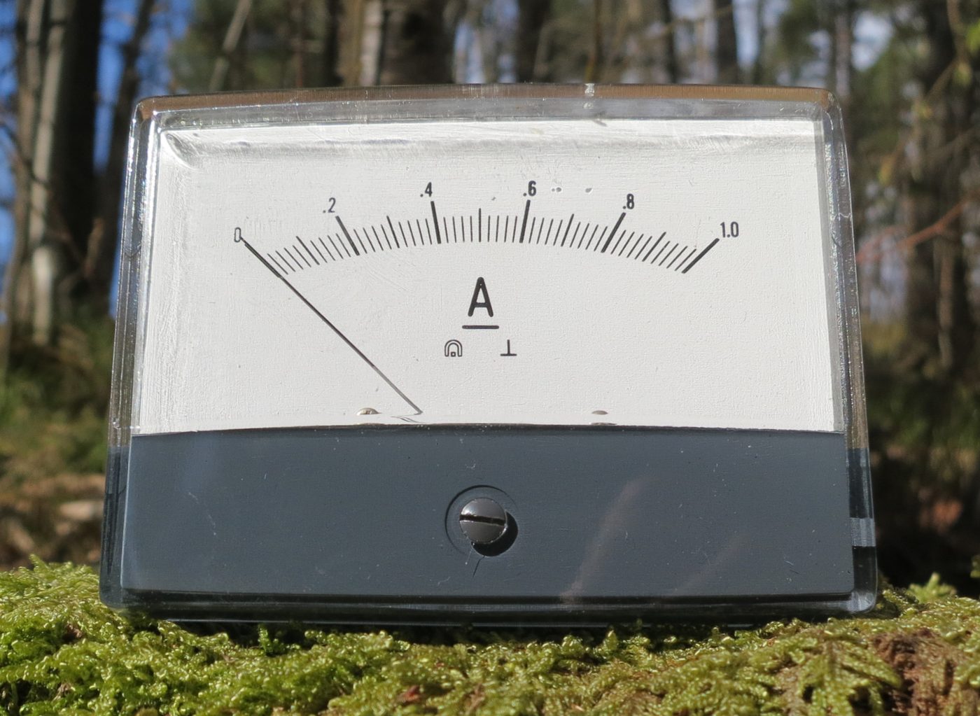
Analog ammeter measuring current (Source: Wikimedia Commons)
Resistance is the opposition a material offers to the flow of current, and its SI unit is the ohm (Ω). Resistance values affect circuit performance and component functionality. Example: a SACCO's matatu with dim headlights is found to have a corroded connector with high resistance, which reduces the current reaching the bulbs.
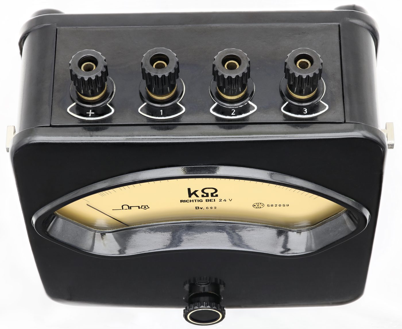
Analog ohmmeter with multiple terminals (Source: Wikimedia Commons)
Voltage is the electric potential difference, or electromotive force, that pushes current round a circuit, and its SI unit is the volt (V). Voltage levels determine battery charge and sensor operation in vehicles. Example: a hotel's shuttle van that cranks slowly is found to have a battery reading of only 11.6 V, which shows that it is discharged.
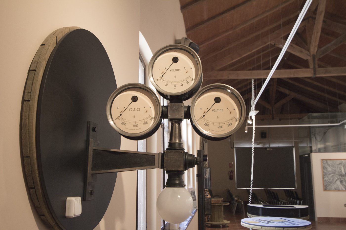
Analog voltmeters mounted on a wall (Source: Wikimedia Commons)
Measuring electrical quantities accurately in vehicles requires using SI units with calibrated instruments such as multimeters and oscilloscopes. Automotive technicians in Kenya must be proficient in interpreting these measurements to maintain electrical system integrity.
Prefix multipliers modify base SI units to express large or small quantities conveniently. Automotive engineers must understand these prefixes to interpret sensor outputs and electrical parameters accurately.
Converting between units and prefixes is essential when dealing with diverse electrical components and measuring instruments in vehicles.
Example 1: Converting milliamperes to amperes
Given: 500 milliamperes (mA)
Formula: 1 A = 1000 mA
Substitution: amperes = 500 ÷ 1000
Working: 500 ÷ 1000 = 0.5
Result: 0.5 A
Example 2: Converting kiloohms to ohms
Given: 2.5 kiloohms (kΩ)
Formula: 1 kΩ = 1000 Ω
Substitution: ohms = 2.5 × 1000
Working: 2.5 × 1000 = 2500
Result: 2500 Ω
Example 3: Converting microfarads to farads
Given: 220 microfarads (μF)
Formula: 1 μF = 10⁻⁶ F
Substitution: farads = 220 × 10⁻⁶
Working: 220 × 0.000001 = 0.00022
Result: 0.00022 F
Example 4: Converting megaohms to ohms
Given: 20 megaohms (MΩ)
Formula: 1 MΩ = 1,000,000 Ω
Substitution: ohms = 20 × 1,000,000
Working: 20 × 1,000,000 = 20,000,000
Result: 20,000,000 Ω
Example 5: Converting hours to seconds for energy calculations
Given: 3 hours
Formula: 1 hour = 3600 seconds
Substitution: seconds = 3 × 3600
Working: 3 × 3600 = 10,800
Result: 10,800 s
These examples reflect typical conversions encountered in Kenyan automotive workshops, such as those at CMC Motors Group and Simba Corporation.
Create a free account to open more of this chapter.
Free: practical guides, quick cards, workplace scenarios and more.
Create a free accountThis chapter introduced the fundamental SI units essential for understanding electrical quantities, including power measured in watts, current in amperes, resistance in ohms, and voltage in volts. It explored the properties of conductors and insulators, highlighting the differences between metals and non-metals and their respective roles in electrical circuits. Key electrical quantities such as charge, force, work, and power were defined and their units explained, with calculations demonstrating their practical use. The chapter detailed Ohm’s Law, emphasizing its importance in relating voltage, current, and resistance, and provided examples of its application in solving electrical problems. It also covered basic electrical and electronic measurement techniques, focusing on the use of instruments like multimeters, oscilloscopes, and ammeters. Finally, the importance of measurement accuracy and instrument calibration was discussed to ensure reliable and precise readings in electrical work.
A car battery supplies a current of 20 A to the starter motor. Calculate the charge that flows through the motor in 5 seconds. (2 marks)
An automotive circuit operates at a voltage of 12 V and draws a current of 3 A. Calculate the power consumed by the circuit. (2 marks)
Type: Individual
| Tools & Equipment | Materials |
|---|---|
| Digital multimeter (with continuity test function) | Copper wire samples |
| Assorted test leads with alligator clips | Aluminium sheet sample |
| Insulating gloves | Plastic sheet sample |
| Insulating mat | Rubber sheet sample |
| Glass sheet sample | |
| Iron nail samples | |
| Wood block sample |
| S/N | Item | Quantity |
|---|---|---|
| 1 | Digital multimeter (with continuity test function) | 1 Pc per Candidate |
| 2 | Assorted test leads with alligator clips | 1 Set per Candidate |
| 3 | Samples of copper wire (length 150mm, diameter 1.5mm) | 2 Pcs per Candidate |
| 4 | Samples of aluminium sheet (50mm x 50mm x 1mm) | 1 Pc per Candidate |
| 5 | Samples of plastic sheet (50mm x 50mm x 1mm) | 1 Pc per Candidate |
| 6 | Samples of rubber sheet (50mm x 50mm x 1mm) | 1 Pc per Candidate |
| 7 | Samples of glass sheet (50mm x 50mm x 2mm) | 1 Pc per Candidate |
| 8 | Samples of iron nail (length 75mm, diameter 5mm) | 2 Pcs per Candidate |
| 9 | Samples of wood block (50mm x 50mm x 20mm) | 1 Pc per Candidate |
| 10 | Insulating gloves (rubber) | 1 Pair per Candidate |
| 11 | Insulating mat (rubber, 300mm x 300mm) | 1 Pc per Candidate |
| Items to be Evaluated | Marks Available | Marks Obtained | Comments |
|---|---|---|---|
| TASK 1: Preparation and Safety | |||
| Wore insulating gloves and stood on insulating mat before testing (Award 1 mark for each or zero) | 2 | ||
| Checked the digital multimeter for correct operation and set to continuity test mode (Award 2 marks or zero) | 2 | ||
| Organized all test samples and tools neatly on the workbench (Award 1 mark or zero) | 1 | ||
| Sub-Total | 5 | ||
| TASK 2: Conductivity Testing and Classification | |||
| Tested copper wire samples correctly using continuity test and recorded results (Award 3 marks or zero) | 3 | ||
| Tested aluminium sheet sample correctly and recorded results (Award 2 marks or zero) | 2 | ||
| Tested iron nail samples correctly and recorded results (Award 3 marks or zero) | 3 | ||
| Tested plastic, rubber, glass and wood samples correctly and recorded results (Award 1.5 marks for each correct test or zero) | 6 | ||
| Classified each sample accurately as conductor or insulator based on test results (Award 1 mark for each correct classification or zero) | 4 | ||
| Sub-Total | 18 | ||
| TASK 3: Cleanup and Documentation | |||
| Turned off and safely stored the digital multimeter and test leads (Award 1 mark or zero) | 1 | ||
| Disposed or stored material samples as instructed (Award 1 mark or zero) | 1 | ||
| Completed a clear and accurate test record sheet documenting results and classifications (Award 3 marks or zero) | 3 | ||
| Sub-Total | 5 | ||
| PRODUCT CHECKLIST | |||
| Test record sheet showing correct continuity readings for all samples (Award 5 marks or zero) | 5 | ||
| Accurate classification of all samples as conductors or insulators (Award 5 marks or zero) | 5 | ||
| Sub-Total | 10 | ||
| GRAND TOTAL | 38 | ||
Type: Individual
| Tools & Equipment | Materials |
|---|---|
| Ammeter (0-10 A range) | 1.5 V Battery |
| Multimeter (with ammeter function) | Resistor 10 Ω, 5 W |
| Screwdriver (flat head) | Connecting wires with alligator clips |
| Wire stripper/cutter | Breadboard or Circuit Board |
| S/N | Item | Quantity |
|---|---|---|
| 1 | Ammeter (0-10 A range) | 1 Pc per Candidate |
| 2 | Multimeter (with ammeter function) | 1 Pc per Candidate |
| 3 | 1.5 V Battery | 2 Pcs per Candidate |
| 4 | Resistor 10 Ω, 5 W | 1 Pc per Candidate |
| 5 | Connecting wires with alligator clips | 5 Pcs per Candidate |
| 6 | Breadboard or Circuit Board | 1 Pc per Candidate |
| 7 | Screwdriver (flat head) | 1 Pc per Candidate |
| 8 | Wire stripper/cutter | 1 Pc per Candidate |
| 9 | Personal Protective Equipment (PPE) – Safety gloves and Safety boots | 1 Set per Candidate |
| Items to be Evaluated | Marks Available | Marks Obtained | Comments |
|---|---|---|---|
| TASK 1: Circuit Assembly and Current Measurement | |||
| Wore the required personal protective equipment (safety gloves and boots) (Award 1 mark for each PPE worn) | 2 | ||
| Gathered all required tools and materials before starting the task (Award 1 mark each for tools and materials gathered) | 2 | ||
| Prepared the circuit components and breadboard for assembly (Award 2 marks for correct preparation or zero) | 2 | ||
| Connected the two 1.5 V batteries in series correctly to provide 3 V (Award 3 marks for correct series connection or zero) | 3 | ||
| Connected the 10 Ω resistor in series on the breadboard (Award 3 marks for correct resistor placement or zero) | 3 | ||
| Connected the ammeter correctly in series with the resistor and power source (Award 5 marks for correct ammeter connection or zero) | 5 | ||
| Took a clear and accurate current measurement using the ammeter (Award 5 marks for correct measurement technique and reading or zero) | 5 | ||
| Recorded the measured current correctly in amperes (A) (Award 3 marks for correct recording or zero) | 3 | ||
| Disconnected the circuit safely after measurement (Award 2 marks for safe disconnection or zero) | 2 | ||
| Completed the task within the allocated time (Award 3 marks for timely completion or zero) | 3 | ||
| Performed housekeeping by cleaning the workspace and storing tools properly (Award 2 marks for proper housekeeping or zero) | 2 | ||
| Sub-Total | 32 | ||
| PRODUCT CHECKLIST | |||
| Correct series connection of batteries, resistor, and ammeter as per circuit diagram (Award 5 marks if circuit connections are correct or zero) | 5 | ||
| Ammeter connected in series correctly without bypassing the resistor (Award 5 marks if ammeter is correctly connected in series or zero) | 5 | ||
| Measured current value is within ±5% of the theoretical current (I = V/R = 3 V / 10 Ω = 0.3 A) (Award 6 marks for measurement within tolerance or zero) | 6 | ||
| Recorded current value clearly and legibly in amperes (Award 2 marks for clear recording or zero) | 2 | ||
| Sub-Total | 18 | ||
| GRAND TOTAL | 50 | ||
At the start of this chapter we promised you would be able to:
Tick each one you can genuinely do.
So, are you there yet?
You're competent when you can confidently do 50% or more of what this chapter promised.
Sign in to record how you're doing.