Technical drawing is an essential skill for automotive engineering technologists in Kenya, enabling them to communicate complex ideas clearly and precisely. Producing solid geometry drawings is particularly important in automotive design and manufacturing, where components often involve intricate three-dimensional shapes. This chapter focuses on sketching and drawing patterns of common solid geometries such as cylinders, prisms, and pyramids, which form the basis of many automotive parts and assemblies.
4.1 Sketches and Drawings of Patterns
In automotive engineering, the ability to produce accurate sketches and drawings of solid geometric patterns is vital for creating prototypes, manufacturing parts, and conducting quality control. Patterns represent the development of surfaces when solids are unfolded into two dimensions, facilitating the fabrication process. Mastery of cylinders, prisms, and pyramids as fundamental solids enables engineers to handle more complex shapes encountered in vehicle components such as engine cylinders, chassis beams, and suspension parts.
4.1.1 Cylinders
Cylinders are among the most common solids in automotive engineering, representing components like pistons, engine cylinders, and hydraulic parts. Understanding how to draw and develop cylinder patterns accurately is crucial for fabrication, repair, and reverse engineering tasks.
Characteristics of Cylinders
-
Circular Bases: Cylinders have two parallel circular bases of equal size connected by a curved surface, which is essential for parts like pistons where uniform diameter is critical.
-
Axis: The straight line joining the centers of the two bases defines the axis, which determines the cylinder’s orientation and length.
- Height: The perpendicular distance between the bases is the height, influencing volume and surface area critical in fluid dynamics.
- Curved Surface: The lateral surface is curved and can be developed into a rectangle when unrolled, used in pattern making.
- Closed or Open Ends: Cylinders can be closed with bases or open-ended, affecting their application in automotive exhaust or intake systems.
Importance of Cylinder Patterns in Automotive Engineering
- Fabrication Accuracy: Precise patterns ensure seamless welding or joining of cylindrical parts, preventing leaks in hydraulic or pneumatic systems.
- Material Estimation: Patterns help calculate the sheet metal size required before forming, reducing waste and cost.
- Repair and Replacement: Accurate drawings guide technicians in manufacturing replacement parts for engine components.
- Quality Control: Patterns assist in inspecting manufactured parts for dimensional conformity.
- Design Communication: They provide a clear visual reference for engineers and fabricators during the production process.
Procedure for Drawing Cylinder Patterns
- Draw the Front Elevation: Sketch two parallel horizontal lines representing the cylinder’s height. Draw two concentric circles at the base line for the bottom face.
- Project the Top View: From the front elevation, project vertical lines upwards and draw the top circular base parallel to the bottom.
- Draw the Development Rectangle: Calculate the circumference of the base circle using Circumference = π × Diameter.
- Mark the Rectangle's Length: Use the cylinder height as the rectangle’s length and the circumference as its width.
- Divide the Rectangle: Mark equal divisions along the width to transfer points for accurate curve projection.
- Draw the Curved Edge: Connect the divisions with smooth curves to represent the cylinder’s curved surface when flattened.
- Add Allowances: Include seam and overlap allowances for fabrication.
Common Errors in Cylinder Pattern Drawing
- Incorrect Circumference Calculation: Using diameter instead of radius or inaccurate π value leads to wrong pattern width.
- Misalignment of Views: Failure to project the top and front views correctly causes distorted patterns.
- Omission of Allowances: Neglecting seam and overlap allowances results in parts that cannot be assembled.
- Unequal Division Marks: Uneven spacing in the development rectangle distorts the curved surface.
- Ignoring Scale: Not using consistent scales between views causes dimensional mismatches.
4.1.2 Prisms
Prisms appear frequently in automotive structures such as chassis members, brackets, and support beams. Understanding their geometric properties and development patterns is critical for sheet metal fabrication and component assembly.
Types and Characteristics of Prisms
- Right Prism: The lateral faces are rectangles perpendicular to the base, common in structural automotive parts.
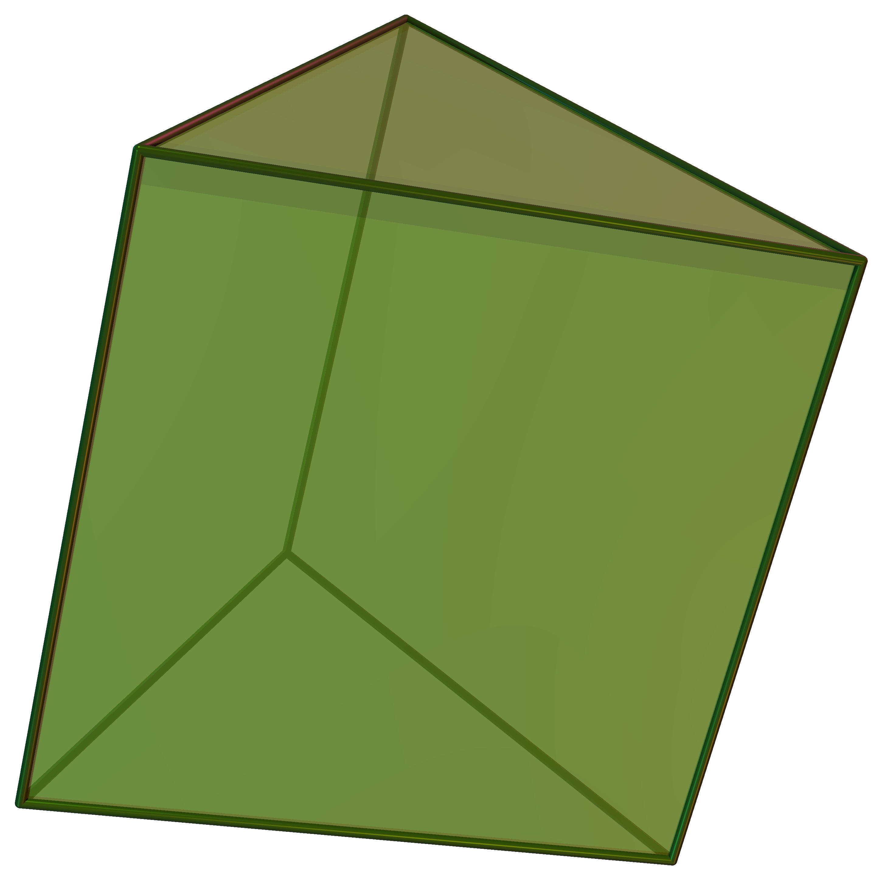
A right prism geometric solid (Source: Wikipedia (Triangular prism))
- Oblique Prism: The lateral faces are parallelograms, used where angled supports are necessary.
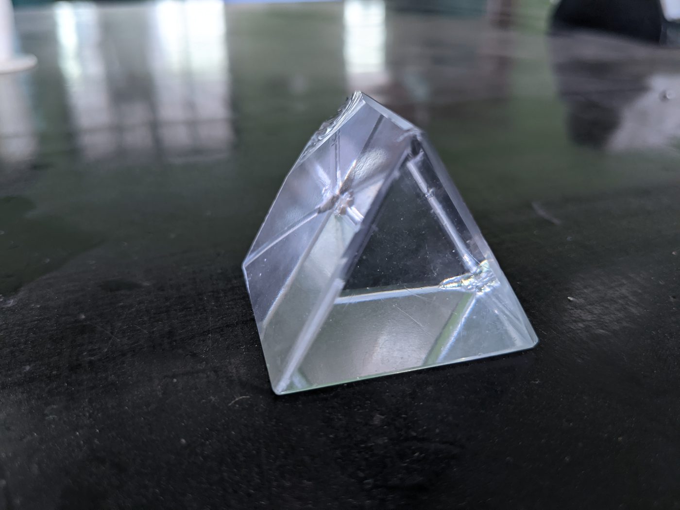
Clear plastic oblique prism on table (Source: Wikimedia Commons)
- Regular Prism: Bases are regular polygons, offering uniformity in design, such as hexagonal nuts.
-
Irregular Prism: Bases are irregular polygons, often custom-designed parts.
-
Faces and Edges: Prisms have two congruent polygonal bases connected by parallelogram faces, defining the shape’s complexity.
Importance of Prism Patterns in Automotive Engineering
- Structural Fabrication: Patterns assist in cutting and bending sheet metals to form beams and brackets.
- Component Integration: Accurate drawings ensure components fit correctly in assemblies like suspension linkages.
- Material Optimization: Development patterns minimize scrap during fabrication.
- Inspection and Quality Assurance: Patterns help verify dimensional accuracy of fabricated prisms.
- Prototyping: Engineers use patterns to create models for testing mechanical properties.
Procedure for Drawing Prism Patterns
- Draw the Front Elevation: Sketch the prism’s height and the polygonal base shape.
- Project the Top View: Transfer the base shape accurately above the front elevation.
- Draw the Development Line: Draw a straight horizontal line equal to the perimeter of the base polygon.
- Divide the Line: Mark the length of each side of the base polygon along the development line.
- Draw Rectangular Faces: From each division point, draw perpendicular lines equal to the prism’s height.
- Connect the Top Points: Join the top points of the perpendicular lines to complete the pattern.
- Include Allowances: Add seam and overlap allowances for welding or riveting.
Challenges and How to Overcome Them in Prism Pattern Drawing
Challenges
- Complex Base Shapes: Irregular polygons complicate perimeter measurement and accurate division.
- Projection Errors: Misalignment between views causes distorted patterns.
- Allowance Miscalculations: Incorrect seam allowances lead to assembly issues.
- Scale Inconsistencies: Using different scales for views causes dimensional errors.
- Curve Approximation: For prisms with curved edges, approximations may reduce accuracy.
How to Overcome
- Use Accurate Measuring Tools: Employ digital calipers and protractors for precise base dimensions.
- Apply Standard Projection Methods: Follow BS 8888 or ISO 128 standards for orthographic projections.
- Double-Check Allowances: Confirm seam and overlap measurements before finalizing drawings.
- Maintain Consistent Scales: Use uniform scale ratios across all views.
- Use CAD Software: For complex bases, CAD tools help generate precise patterns.
4.1.3 Pyramids
Pyramids, though less common than cylinders and prisms, are important for certain automotive components like roof supports or aerodynamic fairings. Understanding their pattern development aids in manufacturing custom sheet metal parts.
Properties and Types of Pyramids
- Square-Based Pyramid: Common base shape with four triangular lateral faces converging at the apex.
-
Triangular Pyramid (Tetrahedron): Simplest pyramid with three triangular lateral faces.
-
Regular Pyramid: Base is a regular polygon, ensuring symmetry.
- Irregular Pyramid: Base is an irregular polygon, requiring careful pattern development.
- Apex and Slant Edges: The apex is the point where all lateral faces meet; slant edges define the lateral face inclinations.
Significance of Pyramid Patterns in Automotive Engineering
- Sheet Metal Fabrication: Patterns guide cutting and folding for aerodynamic panels.
- Structural Components: Used in designing support structures with tapered profiles.
- Prototyping and Model Making: Allows visualization of complex shapes before production.
- Material Efficiency: Helps minimize waste during pattern cutting.
- Assembly Guidance: Ensures accurate alignment of faces during welding or riveting.
Procedure for Drawing Pyramid Patterns
- Draw the Front Elevation: Sketch the base polygon and apex point above it.
- Project the Top View: Draw the base polygon in plan view.
- Draw the Development Line: Calculate the perimeter of the base polygon and draw a horizontal line of equal length.
- Divide the Line: Mark the lengths of the base sides along the development line.
- Draw Triangular Faces: From each division point, draw triangles representing the lateral faces using slant height measurements.
- Connect the Triangles: Join the triangles along common edges to form the pattern.
- Add Seam Allowances: Include allowances for joining edges.
Typical Mistakes in Pyramid Pattern Drawing
- Incorrect Slant Height Measurement: Results in distorted lateral faces.
- Misplaced Apex Projection: Causes inaccurate face angles.
- Inaccurate Base Perimeter: Leads to improper pattern length.
- Omission of Seam Allowances: Prevents proper assembly.
- Poor Division of Development Line: Distorts face shapes.
Practice Questions
-
Draw the front elevation and top view of a cylinder with a diameter of 80mm and height of 150mm. Then, construct its development pattern including seam allowance of 10mm. (20 marks)
-
A right prism has a hexagonal base with 30mm sides and height 100mm. Draw the front elevation, top view, and develop the pattern with all necessary allowances. (25 marks)
-
Sketch and develop the pattern of a square-based pyramid with base side length 60mm and slant height 80mm. Include allowances for joining. (20 marks)
-
Explain five common errors encountered during cylinder pattern development and how they affect the fabrication process. (10 marks)
The rest of this chapter
🔒Create a free account to open more of this chapter.
Free: practical guides, quick cards, workplace scenarios and more.
Create a free account 🔒4.2 Solids Drawings
In automotive engineering technology, solid geometry drawings are essential for visualizing and communicating the shapes of components such as engine parts, transmission casings, and suspension elements. Accurate solid drawings enable technicians and engineers…
🔒4.3 Development and Interpenetrations of Solids
In automotive engineering technology, understanding how different solid shapes interact is crucial when designing complex components such as engine blocks, exhaust manifolds, and chassis parts. The process of developing surfaces and analyzing interpenetrations…
🔒4.4 Different symbols and abbreviations
In automotive engineering technical drawing, symbols and abbreviations are essential for efficient communication of detailed information. Kenyan automotive engineers use these conventions to convey complex data succinctly on drawings, ensuring clarity and stan…
🔒4.5 Auxiliary views and true shapes of truncated solids
In automotive engineering technology, auxiliary views are crucial for accurately representing complex parts that cannot be fully described by standard orthographic projections. Truncated solids such as cylinders, prisms, and pyramids frequently appear in compo…
Chapter Summary
This chapter covered the essential techniques for producing solid geometry drawings, beginning with sketches and drawings of basic patterns such as cylinders, prisms, and pyramids. It then progressed to detailed solid drawings of prisms, cones, and cylinders, emphasizing accurate representation and dimensioning. The development and interpenetration of solids were explored, focusing on how different solids like cylinders and prisms intersect and how to construct these intersections accurately. Various symbols and abbreviations used in technical drawings were explained to ensure clarity and standardization. The chapter also introduced auxiliary views and methods for obtaining true shapes of truncated solids, including truncated cylinders, prisms, and pyramids. Throughout, the importance of following established drawing conventions and standards was highlighted to achieve precise and professional technical drawings.
Self-Assessment
🔒 PDFDownload this self-assessment, with answers
A. Written Assessment
- Which line type is typically used to represent hidden edges in solid geometry drawings? (1 mark)
- Name the three principal views required to fully represent a prism in technical drawing. (2 marks)
🔒20 more in this section.
Chapter Examination Questions
🔒 PDFDownload these examination questions, with worked answers
SECTION A (40 Marks) - Answer ALL Questions
- In an automotive workshop in Nairobi, explain the key steps to sketch the development pattern of a cylinder used in an exhaust muffler. (4 marks)
- Differentiate between the development of a prism and a pyramid in solid geometry drawings. (4 marks)
🔒18 more in this section.
Chapter Practical Activities
Practical 1: Sketching and Drawing Solid Geometry Patterns
Automotive Engineering Technology · Level 6
Technical Drawing
PRACTICAL ASSESSMENT
TIME: 4 HOURS
⬇ PDFCandidate Instructions (Candidate Tool)
Type: Individual
INSTRUCTIONS TO CANDIDATE:
1. You are required to perform the following task:
i. Produce a detailed drawing and freehand sketch of a solid cube pattern 100mm x 100mm x 100mm as per the provided working drawing.
2. You have been provided with the following resources for the practical task:
| Tools & Equipment | Materials |
|---|
| T-square | A2 Drawing paper |
| Engineering set | Rewritable CD |
| Set squares | Printing Papers |
| Assorted pencils: 2H, 4H and HB | |
| Eraser | |
| Masking tape | |
| Computer installed with AutoCAD | |
| Printer | |
⬇ PDFResources Required (Cutting List)
| S/N | Item | Quantity |
|---|
| 1 | A2 Drawing paper | 1 Pc per Candidate |
| 2 | T-square | 1 Pc per Candidate |
| 3 | Engineering set | 1 Pc per Candidate |
| 4 | Set squares | 1 Pair per Candidate |
| 5 | Assorted pencils: 2H, 4H and HB | 1 Pc each per Candidate Total 3 Pcs |
| 6 | Eraser and Masking tape | 1 Pc per Candidate |
| 7 | Rewritable CD | 1 Pc per Candidate |
| 8 | Computer installed with AutoCAD | 1 Pc per Candidate |
| 9 | Printing Papers | Sufficient |
| 10 | Drawing Tables | 1 Pc per Candidate |
| 11 | Printer | 1 Pc per 5 Candidates |
⬇ PDFAssessor Guide
| Items to be Evaluated | Marks Available | Marks Obtained | Comments |
|---|
| TASK 1: Freehand Sketching of Solid Cube Pattern |
Candidate dons appropriate PPE before starting the sketch
(Award 1 mark for correct PPE use or zero) | 1 | | |
Candidate accurately sets out the sketch dimensions freehand on A2 paper
(Award 1 mark each for length, width, and height accuracy) | 3 | | |
Candidate maintains correct proportions and angles in the freehand sketch
(Award 2 marks for correct perspective and proportion or zero) | 2 | | |
Candidate uses correct line weights and pencil grades for sketch clarity
(Award 2 marks for appropriate use of 2H, 4H, HB pencils or zero) | 2 | | |
Candidate completes the freehand sketch within the allotted time
(Award 1 mark for timely completion or zero) | 1 | | |
| Sub-Total | 9 | | |
| TASK 2: Detailed Drawing of Solid Cube Pattern Using AutoCAD |
Candidate correctly sets up the drawing sheet and scale in AutoCAD
(Award 2 marks for correct sheet setup or zero) | 2 | | |
Candidate accurately inputs the cube dimensions 100mm x 100mm x 100mm
(Award 1 mark each for length, width, and height accuracy) | 3 | | |
Candidate produces orthographic views with clear line types and annotations
(Award 3 marks for correct top, front, and side views or zero) | 3 | | |
Candidate saves drawing correctly on the rewritable CD
(Award 1 mark for proper saving or zero) | 1 | | |
Candidate prints the drawing clearly and labels it appropriately
(Award 2 marks for clear printout and correct labeling or zero) | 2 | | |
| Sub-Total | 11 | | |
| PRODUCT CHECKLIST |
Freehand sketch dimensions match 100mm x 100mm x 100mm within ±5mm tolerance
(Award 3 marks for all dimensions within tolerance or zero) | 3 | | |
Freehand sketch shows correct solid cube shape with proper proportions and angles
(Award 2 marks for correct shape or zero) | 2 | | |
AutoCAD drawing includes accurate orthographic views (top, front, side) to scale
(Award 4 marks for complete and accurate views or zero) | 4 | | |
Drawings are neat, labeled, and free from errors or smudges
(Award 3 marks for neatness and labeling or zero) | 3 | | |
| Sub-Total | 12 | | |
| GRAND TOTAL | 32 | | |
ASSESSMENT OUTCOME: ☐ Competent ☐ Not Yet Competent (competent if at least 50%)
Practical 2: Detailed Technical Drawing of a Cylinder
Automotive Engineering Technology · Level 6
Technical Drawing
PRACTICAL ASSESSMENT
TIME: 4 HOURS
⬇ PDFCandidate Instructions (Candidate Tool)
Type: Individual
INSTRUCTIONS TO CANDIDATE:
1. You are required to perform the following task:
i. Prepare detailed technical drawings of a cylinder 120mm diameter and 200mm height showing all relevant views as per the provided working drawing.
2. You have been provided with the following resources for the practical task:
| Tools & Equipment | Materials |
|---|
| T-square | A2 Drawing paper |
| Engineering set | Printing Papers |
| Assorted pencils: 2H, 4H and HB | Rewritable CD |
| Eraser and Masking tape | |
| Set squares | |
| Computer installed with AutoCAD | |
| Drawing Table | |
| Printer | |
⬇ PDFResources Required (Cutting List)
| S/N | Item | Quantity |
|---|
| 1 | A2 Drawing paper | 1 Pc per Candidate |
| 2 | Rewritable CD | 1 Pc per Candidate |
| 3 | Computer installed with AutoCAD | 1 Pc per Candidate |
| 4 | Printing Papers | Sufficient |
| 5 | Drawing Table | 1 Pc per Candidate |
| 6 | Printer | Shared |
| 7 | T-square | 1 Pc per Candidate |
| 8 | Engineering set | 1 Pc per Candidate |
| 9 | Assorted pencils: 2H, 4H and HB | 1 Pc each per Candidate Total 3 Pcs |
| 10 | Eraser and Masking tape | 1 Pc per Candidate |
| 11 | Set squares | 1 Pair per Candidate |
⬇ PDFAssessor Guide
| Items to be Evaluated | Marks Available | Marks Obtained | Comments |
|---|
| TASK 1: Drawing Preparation and Layout |
Uses correct PPE before starting the drawing task
(Award 1 mark for correct PPE use or zero) | 1 | | |
Sets drawing paper properly on the drawing table using masking tape
(Award 1 mark for proper setup or zero) | 1 | | |
Selects appropriate drawing tools and materials
(Award 1 mark for correct tools/materials or zero) | 1 | | |
Accurately scales and lays out the cylinder dimensions on paper
(Award up to 3 marks for correct scaling and layout) | 3 | | |
Draws the cylinder’s front elevation accurately
(Award up to 4 marks for neat and accurate elevation drawing) | 4 | | |
Draws the top view (plan) of the cylinder correctly
(Award up to 4 marks for neat and accurate plan drawing) | 4 | | |
Draws the side view of the cylinder correctly
(Award up to 3 marks for neat and accurate side view) | 3 | | |
Applies correct line types and weights as per technical drawing standards
(Award up to 2 marks for correct line types and weights) | 2 | | |
Uses appropriate dimensioning techniques and places dimensions clearly
(Award up to 3 marks for correct dimensioning) | 3 | | |
Checks and corrects errors before finalizing the drawing
(Award 2 marks for evidence of checking and corrections) | 2 | | |
Saves and prints the drawing using AutoCAD as per instructions
(Award 2 marks for correct saving and printing procedure) | 2 | | |
| Sub-Total | 26 | | |
| PRODUCT CHECKLIST |
Cylinder diameter dimension is accurately shown as 120mm ±1mm
(Award 3 marks for accurate diameter dimensioning or zero) | 3 | | |
Cylinder height dimension is accurately shown as 200mm ±1mm
(Award 3 marks for accurate height dimensioning or zero) | 3 | | |
All views (front elevation, top plan, side elevation) are correctly drawn and aligned
(Award up to 5 marks for correctness and alignment of views) | 5 | | |
Drawing is neat, clean, and free from smudges or unnecessary marks
(Award up to 3 marks for neatness and presentation) | 3 | | |
Lines are straight and uniform thickness as per standards
(Award up to 3 marks for line quality) | 3 | | |
Dimensions and annotations are clear and legible
(Award up to 3 marks for clarity and legibility) | 3 | | |
| Sub-Total | 20 | | |
| GRAND TOTAL | 46 | | |
ASSESSMENT OUTCOME: ☐ Competent ☐ Not Yet Competent (competent if at least 50%)
🔒Technical Drawing of a Hexagonal PrismPractical 3
🔒Detailed Technical Drawing of a Square-Based PyramidPractical 4
🔒Technical Drawing of a Cone with Orthographic ViewsPractical 5
🔒Drawing combined solid geometry shapes with orthographic viewsPractical 6
🔒Development of a Cuboid and Cylinder Solid PatternsPractical 7
🔒Interpenetration of Two Cylinders Solid Geometry DrawingPractical 8
🔒Interpenetration of Cylinder to Prism Solid Geometry DrawingPractical 9
🔒Interpenetration Drawing of Two Rectangular PrismsPractical 10
🔒Application of Symbols and Abbreviations on Solid Geometry DrawingsPractical 11
🔒Auxiliary Views and True Shape Drawings of a Truncated Hexagonal PrismPractical 12
🔒Drawing a truncated cylinder with multiple viewsPractical 13
🔒Detailed drawing of a truncated prism 150mm x 100mm x 120mmPractical 14
🔒Technical Drawing of a Truncated PyramidPractical 15
